Maker Pro
Maker Pro

Replacing LCD instrument readout with LED readout.

Hi all,
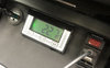
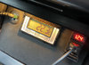
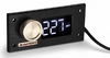
Total newbie at electronics. I am just asking this question to gauge feasibility of my idea. I have a calibratable external temperature gauge for my car, far more accurate than the OEM temp gauge. My problem is the gauge has a rather dull, very lightly backlit lcd screen. I thought it would be a great idea to replace the lcd screen with an led screen so the numbers could be lit. The unit as it is now looks like the first image with the green background. What I would like is red led numbers. Is this feasible or more trouble than its worth?
upload_2020-12-13_22-15-21.png
upload_2020-12-13_22-15-39.png
 

Harald Kapp

Moderator
Moderator
Is this feasible or more trouble than its worth?
It may be feasible but will require considerable effort. The control circuitry for LCDs is very different from the one for LEDs. One would have to decode the LCD signals and convert them to suitable LED signals.
Considering that you had to ask, I doubt this is within your capabilities.

It may be possible and probably easier to increase the brightness of the dull backlight. You'd have to open the display and find the current control for the LED backlight, possibly only one or more resistors. You could then replace the resistor(s) by ones with less resistance to increase brightness.
 
I'd imagine that *most* of the cheap generics, are closer to accurate than the difference between air temp and road temp.

Then again if the interest is accuracy at 0, seems like you could use some pull up/down resistors to accomplish that if there isn't a pot in it to adjust. Having never done this, I wonder if it would make accuracy worse towards the upper end of its range but that may not matter.
 
Low temp accuracy is more important to me. The unit I have has the ability to be calibrated to zero C by immersing the sensor in crushed ice and water. It allows adjustment in steps of .1 C so at least I know it’s accurate at 0 C. It also records max/min temps. As mentioned above, claimed accuracy is different from actual and being able to calibrate. I still haven’t found an alternative so I am considering mounting a small led to shine onto the face of the gauge to improve visibility.
 
. . . . .so I am considering mounting a small led to shine onto the face of the gauge to improve visibility.

That unit is incorporating a TRANSMISSIVE LCD element, vice REFLECTIVE , meaning that it is dependent upon its illumination passing thru it from the BACK of the unit, therefore illumination from the FRONT would only proportionatively diminish its illuminative /contrast capabilities.
Fair enough, sounds like a case of just live with it :)
 
... or put the LED in the back, or do as Harald suggested and increase the existing LED driver current, though I'd want to know what it is using now, as a baseline to determine if you can increase it enough to matter or would just burn up the LED (or possibly it was already overdriven for the design and now suffers output reduction as a result), though you might be able to replace that LED with one having a higher power rating, or look at whether some of the light is being wasted, maybe coat the rear of it with a very thin layer of clear epoxy, let it set up, then epoxy some foil behind it to reflect the light towards the screen more.

Good pics of the internals would have been a better way to start this topic.
 
Last edited by a moderator:
Yeah if you intend to keep using it as-is, I'd leave it alone, though I haven't had problems taking similar things apart, just a matter of whether there is sufficient alignment tabs to hold the display perfectly so the zebra strip lines back up, but then I wouldn't treasure it if it's not bright enough, would just buy the ebay LED type and compare accuracy. Little ventured, little lost if it doesn't get close enough BUT since those use a sensor on a wire, it should not be difficult to resistor-mod them ON the wire, to tweak the 0C accuracy without having to take the assembly itself apart.
 
Reading the instruction sheet on its battery and its lifetime specs, clinch it as using an electro-chemical luminescent panel for its backlight illumination.
So thats pretty much of a situatuation of what they have now given you, is what you gonna get.
The only other question would be as to its installational position ,as reading of the display diminishes rapidly if not being direct, head on viewing.
Thats also specically related as to optimally being located on a downward plane, such as is now being also used by your viewing path to your speed-odo-tachmeter.
IF . . . this might actually find the units CURRENT installed position, as being up at visor height and not being positionally pointed DIRECT head on to you.

If there is being some illumination washout due to daytime ambient light dispersion / flooding , evaluate the use of a hand fab of a lightweight posterboard rectangular light tunnel of the dimensions of the black rectangle dimension currently printed just around the LCD display.

Make it of an ~ 1+ inch heighth and paint it FLAT black both inside and outside and test trial mount it with black tape. If then proving of usable merit, mount with 4 internal corner dots of clear contact cement, silicone rubber or *E2000 adhesive ( * it being my current favorite choice of that family of adhesive. )
 
Last edited:
Hi guys, I think some may have been overthinking it a bit. I’m pretty sure it’s not a transmissible lcd as there is a hotspot on the left hand side of the screen, presumably from a single led. I have fitted a 3 led strip above the screen and with a bit of tweaking I reckon it’s just about perfect. The conditions that I took these photos in were pretty good for viewing the original setup but once light levels went higher it was very difficult to see the numbers. Thanks for your input.
Incidentally, the board is just a template for a Zapco DSP/Amp controller which is being installed soon. The controller will sit below the temperature readout.
 

Attachments

  • original.jpg
    original.jpg
    221.4 KB · Views: 10
  • led lit.jpg
    led lit.jpg
    333.7 KB · Views: 10
  • dsp-z8bt-remote_.png
    dsp-z8bt-remote_.png
    304.7 KB · Views: 10
Last edited:
The way the LCD is illuminated from the rear or side has already been explained.
If you get satisfactory result with some other means then great...but it doesn't change the former.
 
there is a hotspot on the left hand side of the screen, presumably from a single led ***
(That's the source point of the EL light source illuminating into a tapered flexi lucite strip . . . interpret as being of a linear Fresnel design concept.)
*** NOPE . . . . . you . . .[Start 999 11/83rds Font Sizing] . . . . . AIN'T . . . . . [Stop 999 11/83rds Font Sizing] . . . .gonna be getting 24/7 display lighting from ANY LED with a mere AA cell power source . . . .that can last for a YEAR !
 

davenn

Moderator
*** NOPE . . . . . you . . .[Start 999 11/83rds Font Sizing] . . . . . AIN'T . . . . . [Stop 999 11/83rds Font Sizing] . . . .gonna be getting 24/7 display lighting from ANY LED with a mere AA cell power source . . . .that can last for a YEAR !

HUH ??????
 
Top