Maker Pro
Maker Pro

Relay help (opto mos)

Hi all,
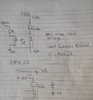
I have attached a schematic of an issue. I have a relay AQY212S, which is fed from a car supply of 12V. This is then switched by a relay. The relay is breaking down, I think it is due to voltage. The relay is rated at max load voltage of 60V.
I am thinking of using a diode suppression on this line, reverse stand off of 60V. Can anyone see any issues? It's a bi direction type.
Thanks in advance.
 

Attachments

  • 1615824294506.jpg
    1615824294506.jpg
    33.4 KB · Views: 15

bertus

Moderator
Hello,

What is the led current?
What is the load of the opto-relay?
When it is inductive, you should use a Bemf diode.

Bertus
 

Attachments

  • aqy21_s.pdf
    600.4 KB · Views: 1
It fails open circuit. it's a photo relay, MOSFET type. The load is power to a couple of circuits, one is a voltage regulator 7805, then this is used to power a opamp (non-inverting), single sided to 5V.
 
Hello,

What is the led current?
What is the load of the opto-relay?
When it is inductive, you should use a Bemf diode.

Bertus
The current of the LED
Hello,

What is the led current?
What is the load of the opto-relay?
When it is inductive, you should use a Bemf diode.

Bertus
Led current is 900uA
Load is 7805 + opamp circuit configured as non inverting amplifier. I do not think it is inductive, the current through the load is not substantial, about 50-100mA. Hence I think it is a voltage spike issue.
 
The current of the LED

Led current is 900uA
Load is 7805 + opamp circuit configured as non inverting amplifier. I do not think it is inductive, the current through the load is not substantial, about 50-100mA. Hence I think it is a voltage spike issue.
Not sure but it may because of the noisy voltage from the car battery. Also does the position of the diode look correct?
 

bertus

Moderator
Hello,

The led current of 900 uA might be marginal.
It is on the border between on and off.
Raise the led current to 3 mA for correct operation.
aqy21_characteristics.png

Bertus
 
Hi all,
Is the placement of the diode in my schematic correct? Or should it go across the output pins of the relay?
Thanks in advance
 
Top