I have been trying to contact a forum member that has done a modification to his pool equipment in order to control it remotely instead of having to go to the box every time and check on the codes. His has released the source code on his github page.
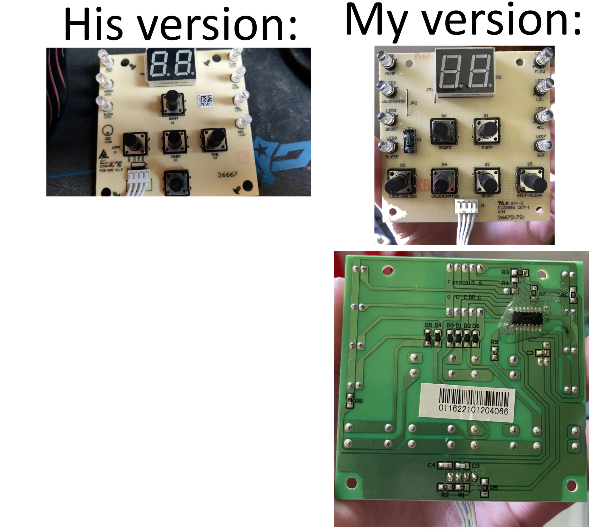
However, I have a different model than he does so I do not think his ESP32 code will work on mine.
His equipment contains a TM1650 for the 2 digit 7 segment display. I am unable to find out if my version has the TM1650 or something else.
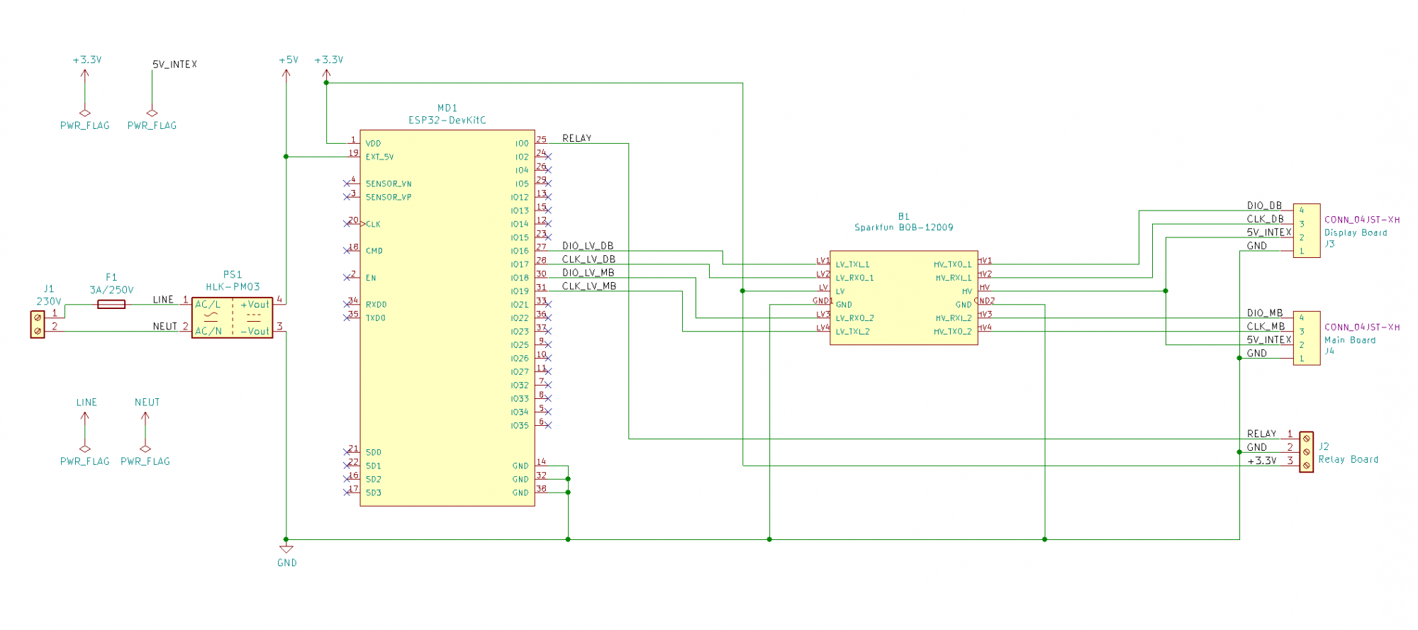
His schematic looks like this:

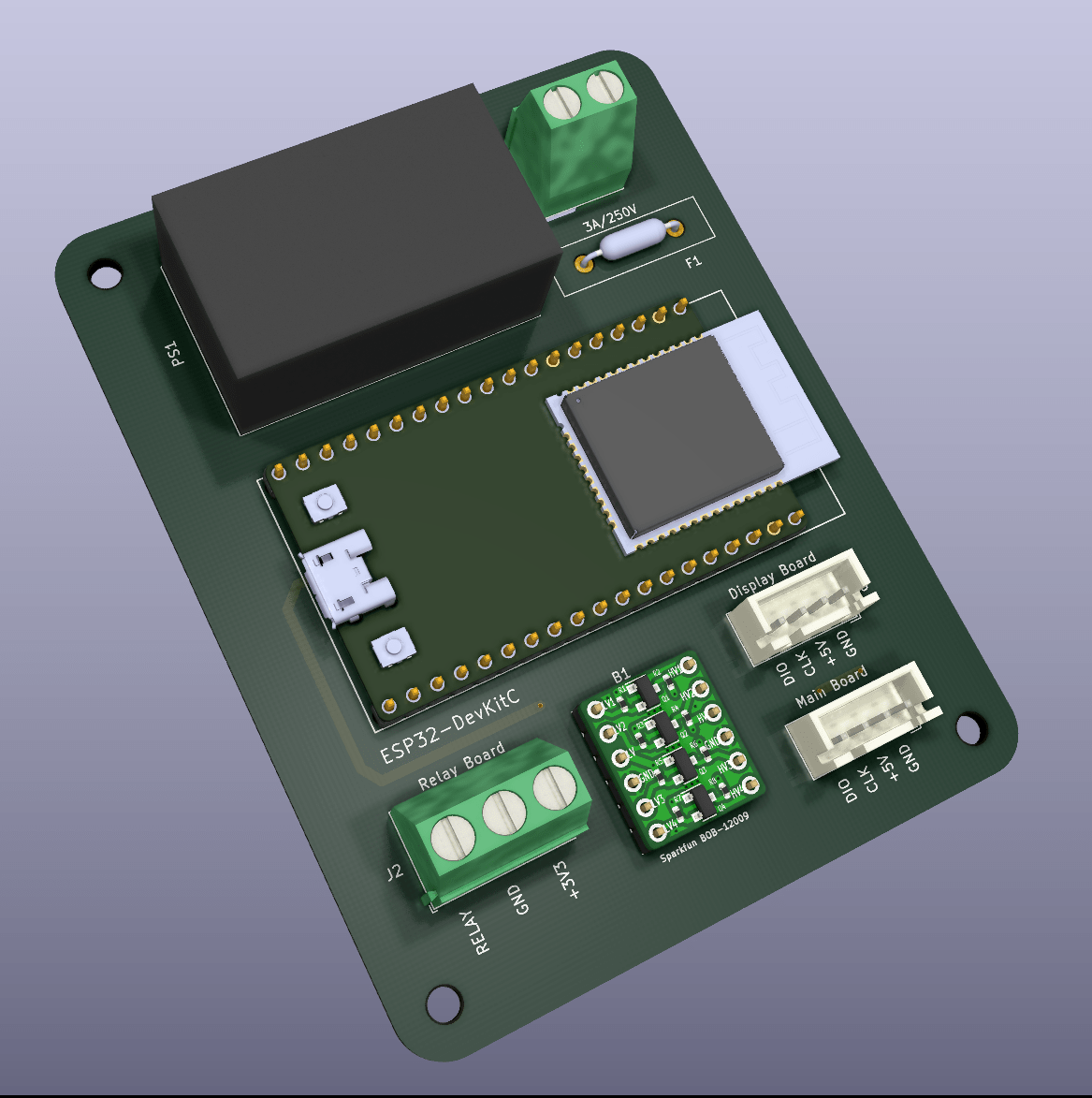
I have all the components that are displayed in the schematic. I have the ESP32 and the Level shifter.

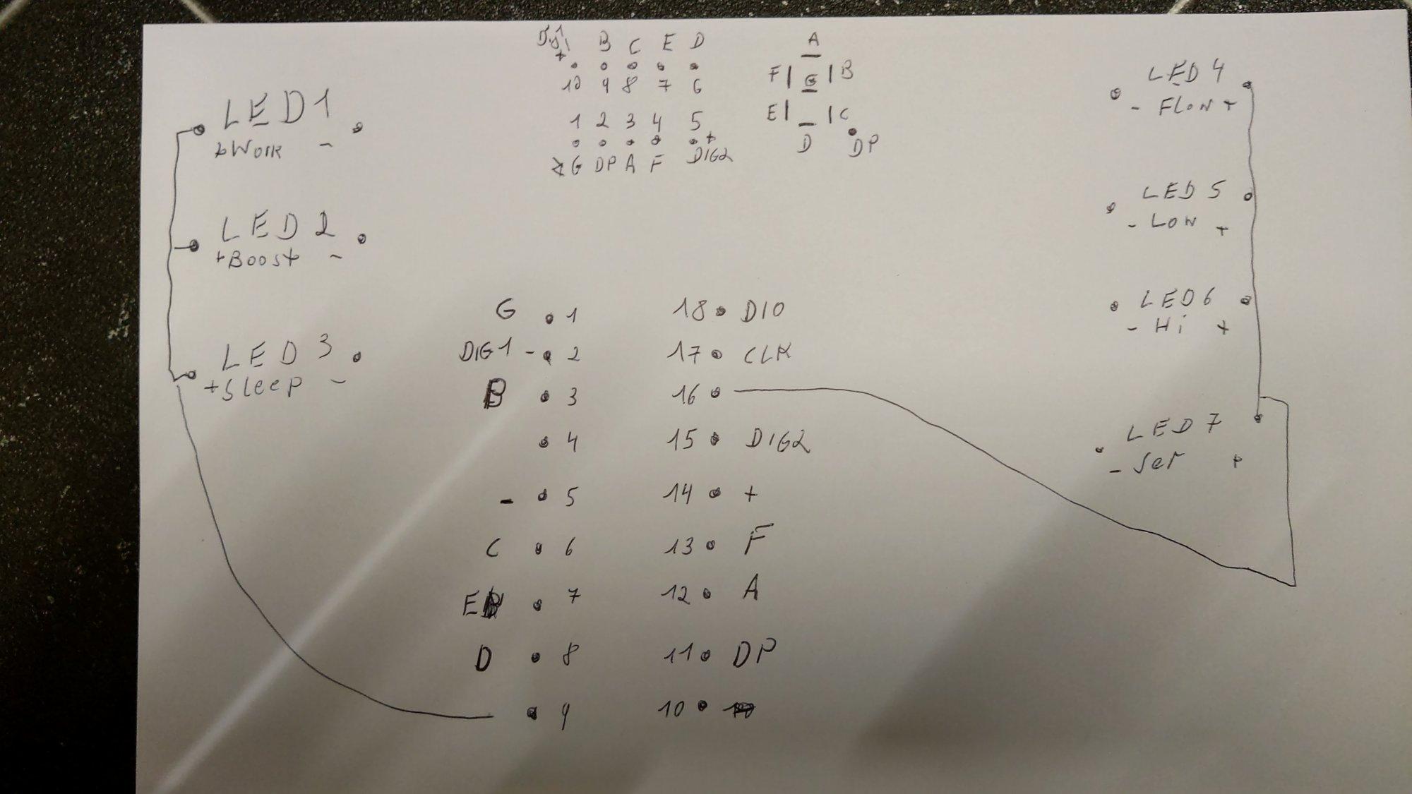
Another forum member had the same chip but some pins were different. His schematic looks like this:
So, since I do not have the same setup as they do is there any IC I can get that would make reading the 2 digit 7 segments easier than trying to read each led and determining what letter/number is being displayed? I can use the 4n25/35 optocoupler to "press" any of the 6 buttons and have an analog read for the 8 LEDs to determine which ones of those are on. The only trouble I foresee is the 2 digit 7 segments reading.
Note: Also posted to the following forums:
Reading 2 digit 7 segments with ESP32
https://www.electro-tech-online.com/threads/reading-2-digit-7-segments-with-esp32.163357/
https://www.eevblog.com/forum/projects/reading-2-digit-7-segments-with-esp32/new/#new
https://www.electronics-lab.com/com.../48746-reading-2-digit-7-segments-with-esp32/
However, I have a different model than he does so I do not think his ESP32 code will work on mine.
His equipment contains a TM1650 for the 2 digit 7 segment display. I am unable to find out if my version has the TM1650 or something else.
His schematic looks like this:


I have all the components that are displayed in the schematic. I have the ESP32 and the Level shifter.

Another forum member had the same chip but some pins were different. His schematic looks like this:

So, since I do not have the same setup as they do is there any IC I can get that would make reading the 2 digit 7 segments easier than trying to read each led and determining what letter/number is being displayed? I can use the 4n25/35 optocoupler to "press" any of the 6 buttons and have an analog read for the 8 LEDs to determine which ones of those are on. The only trouble I foresee is the 2 digit 7 segments reading.
Note: Also posted to the following forums:
Reading 2 digit 7 segments with ESP32
https://www.electro-tech-online.com/threads/reading-2-digit-7-segments-with-esp32.163357/
https://www.eevblog.com/forum/projects/reading-2-digit-7-segments-with-esp32/new/#new
https://www.electronics-lab.com/com.../48746-reading-2-digit-7-segments-with-esp32/
Last edited:


