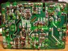
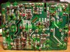
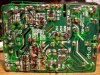
Hi, I've worked on a photo to trace all track (in black) and wrote down component on component side (green, but some component I don't know what they are)... if this is enough to make the diagnosis would be perfect, otherwise I will try to draw the diagram.
If you want a better or bigger photo I can upload it somewhere else.
Thanks,
Sebastian
If you want a better or bigger photo I can upload it somewhere else.
Thanks,
Sebastian


")


