Maker Pro
Maker Pro

Rain Sensor Status

I developed an idea after toying with a two transistor flasher :)

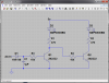
The components are not completely spec'd I just wanted to get some opinions on feasibility. Taking the input from a normal closed switch with 0 VAC - call that the dry state for which I want a green LED to light up, the same switch will provide 3.39VAC when open - call that the wet state for which I want a red LED to light up. From the schematic, I believe I accomplished this goal if LED1 is red, when NC switch is open, 3.39 VAC will become rectified by the diode? (probably very dirty..) and lift the base gate to allow current to flow to ground lighting up LED1 and deactivating LED2(green). When NC closes, no flow through Q1 collector/emitter will turn base of Q2 on allowing current to light up LED2.

Did I get it?
I need help selecting a resistor for Q1/Q2 as well as help selecting appropriate transistors for this switch.

Thanks in advance!

upload_2014-9-8_21-27-45.png
 

(*steve*)

¡sǝpodᴉʇuɐ ǝɥʇ ɹɐǝɥd
Moderator
Q2 is always turned on because its base is tied to its collector, so LED2 is always on.

LED1 will be turned on when the input is more than about 1.2V higher than the negative rail, however there is no base resistor to limit the current through the base/emitter junction. Also you show no common connection for the 3.39VAC.

It would be more conventional to draw Q1 with the collector at the top, emitter at the bottom, and base to the left, with the input coming into the base from the left.

Oh, your regulator's input cap would usually be larger -- perhaps 100uF, and so would the output cap. Maybe 1uF to 100uF as well. Be careful that the input voltage isn't too high for the regulator. A 29.2VAC secondary will result in a DC voltage closer to 41V than 28V. And I think that exceeds the absolute max for the LM7805 as well as being wasteful of 7/8ths of the energy consumed by the device. Something with a secondary rated at around 6VAC to 9VAC would be far better.


Alas, I thought I was close, LOL

The 29.2VAC is the irrigation system's power input, I thought it convenient to use it to power the circuit since it was going to be low current consumption (I believe). That is why I am unable to change it. You are right it is too wasteful, perhaps I should look at a switching regulator. I drew it on the schematic as a transformer, it does come out of the wall wart but goes into the system board, so I am not sure if its filtered and regulated somehow. I assume not since its AC.

The 3.39VAC is common with the 29.2VAC, I omitted it for my own clarity, by I realize it would be hard for you guys to know that, my apologies.

With respect to the transistors, I thought I had it there!!! Tell me if this is better.

upload_2014-9-8_22-25-3.png
 

Harald Kapp

Moderator
Moderator
This circuit still has its drawbacks. If there's no signal on the 3.39V input, a current will flow through R2, LED2, Q2 into the base of Q1 and both LEDs will be on.
Here's a simple circuit that will work (I sketched only the LED and transistor part of it):
bla-png.15102

D1 and C1 are not necessarily required. They serve to rectify and smooth the AC control signal to give a stable display with the LEDs.
 

Attachments

  • bla.png
    bla.png
    38 KB · Views: 374

(*steve*)

¡sǝpodᴉʇuɐ ǝɥʇ ɹɐǝɥd
Moderator
Perhaps you need to tell us exactly what this incoming signal is meant to do.

As the circuit is now, current can flow through R2 and LED2 and then through the base-emitter junction of Q2, through the base-emitter junction of Q1 turning both transistors on. The input signal will probably have no significant effect.

If the input is 3.4VAC in common with one of the AC secondary leads, then the actual voltage depend on whether it is in or out of phase with the other secondary lead. If it is out of phase then the voltage seen here could vary between about +45V and -5V. If it is out of phase, it would vary between perhaps close to zero volts and about +35V.
 

(*steve*)

¡sǝpodᴉʇuɐ ǝɥʇ ɹɐǝɥd
Moderator
Harald beat me to it. While I was sleeping I was wondering if what he drew was what you were after.
 
This circuit still has its drawbacks. If there's no signal on the 3.39V input, a current will flow through R2, LED2, Q2 into the base of Q1 and both LEDs will be on.
Here's a simple circuit that will work (I sketched only the LED and transistor part of it):
bla-png.15102

D1 and C1 are not necessarily required. They serve to rectify and smooth the AC control signal to give a stable display with the LEDs.


Thank you Harald, however as drawn above, I see the switching signal coming in on the left, turning on Q1, which allows current to flow from the top 5v rail through D2 LED to ground, current also flows through R4 turning on Q2 allowing D3 to also turn on. I might not be following the schematic correctly, but it seems that it does not meet the criteria of turning one LED on when signal is present and the other when signal is not. Can you explain this to me? I thought when designing this circuit I would need a flip flop setup. Thanks ever so much!
 
Perhaps you need to tell us exactly what this incoming signal is meant to do.
Hi Steve, the incoming signal is when the rain sensor is wet, the NC switch then opens and 3.39VAC is seen. When the NC is closed and the sensor is dry, there is 0 VAC across the switch. I don't know the inner workings of the controller, but I assume that when the terminal of the controller see's the voltage change it terminates any current irrigation until the sensor is dry.

As the circuit is now, current can flow through R2 and LED2 and then through the base-emitter junction of Q2, through the base-emitter junction of Q1 turning both transistors on. The input signal will probably have no significant effect.
What if I put a diode in between the bases of the transistors? Would that be sufficient to prevent the potential across from the Q2 B-E "leakage"? I didn't realize that there would be leakage when the transistor was off, I thought it was a switch! I think now with the diode in place, when VAC Input is high, Q1 goes high and Q2 goes low (correct terminology?) and when VAC Input is low, Q1 goes low and Q2 goes high - i.e. one lights while the other one doesn't and vice versa.

upload_2014-9-9_8-52-1.png
If the input is 3.4VAC in common with one of the AC secondary leads, then the actual voltage depend on whether it is in or out of phase with the other secondary lead. If it is out of phase then the voltage seen here could vary between about +45V and -5V. If it is out of phase, it would vary between perhaps close to zero volts and about +35V.
The transformer for this unit is a wall wart. I do believe it is rated at 24VAC. I don't believe it has more than one output. I don't think it has more than one secondary. I did check with my dmm and the 3.4VAC was across common.
 

Harald Kapp

Moderator
Moderator
current also flows through R4 turning on Q2 allowing
No, it doesn't. If Q1 is on, the collector-emitter voltage is very low (~0.1V..0.2V). Q2 needs at least 0.6V base-emitter voltage to turn on. Therefore at 0.2V it will be off, no current will flow through R4.
If Q1 is off, the collector-emitter voltage will be ~3.4V (5V - Vled). This will drive a smal current through R4 into the base of Q2 and LED2 will be on. The small current into the base of Q2 also flows through LED1, but will be so small, that you will not notice light emitting from LED1.

I breadboarded your schematic using DC for the switching signal. As you said, there is a small current leaking from Q2's base. Suprisingly, 3ma was large enough to light the LED! I tried putting a diode in series with R4 to prevent this, but it did not work! I thought diodes were one way gates for current to pass through - ideally no resistance in one direction and ideally unlimited resistance in the other. I used a 1N4148 (it looked like a zener, but the body was marked 4148). Any ideas as to why this did not work?
 

(*steve*)

¡sǝpodᴉʇuɐ ǝɥʇ ɹɐǝɥd
Moderator
I breadboarded your schematic using DC for the switching signal. As you said, there is a small current leaking from Q2's base. Suprisingly, 3ma was large enough to light the LED! I tried putting a diode in series with R4 to prevent this, but it did not work! I thought diodes were one way gates for current to pass through - ideally no resistance in one direction and ideally unlimited resistance in the other. I used a 1N4148 (it looked like a zener, but the body was marked 4148). Any ideas as to why this did not work?

If you're talking about Harald's circuit to light one of two LEDs based on the input voltage, then yes, the small current through the base of Q2 via R4 will slightly illuminate D2.

The simple solution is to place a resistor in parallel with D2 such that the voltage drop across it is insufficient to illuminate the LED at all when the transistor is off. If you place a 2k2 resistor between the +5V and the collector of Q1, the voltage drop across this will be about 1V when Q2 is off. This should be insufficient to illuminate the LED. If you're using a red LED here, you could possibly reduce the resistor to 1k.

The reason I suggest placing the resistor from +5V to the collector is that placing it directly across the LED could cause some change in brightness of the LED when it is turned on, if you're not concerned with that, it is perfectly fine to place the resistor directly across the LED.
I will give that a go Steve, thanks!
 
Works great on the breadboard, thanks guys!! Here is a final schematic subject to testing on the live circuit. I only have a 7805, but as was mentioned the Vdrop is quite large. I don't believe that much current is being consumed by the circuit, but a rough guess is not more than 21mA for the LED's, not sure how much the transistors are consuming, but if we guess at 50mA total then the power dissipated by the regulator would be 23.5v * 0.05A = 1.18W. The case to junction states 5 deg C/watt. Can I assume that even if the circuit requires double my guess, the temp would not rise more than about 12 deg C over ambient? Wasteful, but it would work with the parts I have on hand ;-)

upload_2014-9-9_23-34-53.png
 

Harald Kapp

Moderator
Moderator
a small current leaking from Q2's base. Suprisingly, 3ma was large enough to light the LED!
It is not surprising that 3mA light up the LED. What surprises me is that you have 3mA base current at all. With my circuit R4 being 10k and assuming a voltage drop of 2vtotal for LED1 and Q2's base-emitter diode, I arrive at a base current of only 300µA which should not be enough to light the LED visibly.
 

(*steve*)

¡sǝpodᴉʇuɐ ǝɥʇ ɹɐǝɥd
Moderator
Yeah, I was thinking that perhaps a 1k insead of a 10k had been used, but I failed to comment on that.

And I've seen high brightness LEDs (especially those with a narrow half angle) produce quite visible illumination at currents well under 1mA. Naturally a lot also depends on ambient lighting.
 
It is not surprising that 3mA light up the LED. What surprises me is that you have 3mA base current at all. With my circuit R4 being 10k and assuming a voltage drop of 2vtotal for LED1 and Q2's base-emitter diode, I arrive at a base current of only 300µA which should not be enough to light the LED visibly.
You are correct, I had remembered the current for the green LED. The red LED is 165microA - the reason for this is I had used 15k resistors instead of 10k - I had to use a 5v input signal instead of the 3v.
 
Top