This looks doable. It also appears that you are not a total stranger to electronics, given you have already considered using an Arduino board with a quad totem-pole switch, the L293. I, OTOH, know very little about automatic transmissions... Other than what I learned by watching the video tear-down and re-assembly video at the bottom of the page on
this website. Pretty good tutorial, but I think I will leave transmission repair to people like Randy. Plus, I'm a Ford (Found On the Road, Dead) kinda guy.
I will assume that the hydraulic fluid is compressed by a constant-volume pump and that the hydraulic pressure is controlled by by-passing the fluid back to the pump inlet through the pressure-control solenoid valve located in the transmission valve body, thus less pressure when the valve is more open.
Many moons ago (1964 to 1967) I worked on an hydraulically-driven and aimed 20mm Gatling gun mounted at the rear end of B-52H heavy bombers, the AN/ASG-21 Defensive Fire Control System. Our system used a constant-pressure (3000 psig) hydraulic power supply that varied the pressure by using a variable-displacement (swash-plate) multipiston pump, providing about 30 HP, driven with a three-phase, 400 Hz, induction motor. The whole thing, weapon, ammo box, two-axis turret, and hydraulic power supply fit in a volume of less than one cubic meter. Pretty amazing stuff for a twenty year old kid to being playing with! Not to mention then state-of-the-art electronics to make it all play together with combat reliability.
Much to my amazement (because I thought my system was the neatest thing since sliced bread), the remaining hydraulics on the airplane used constant-volume pumps driven mechanically off the eight tubrofan engines. They just used pressure-relief valves near the point of load to bring the pressure down to whatever level was needed, returning the unused fluid volume back to the pumps. I guess this worked well when you had literally hundreds, if not thousands, of feet between pump and actuator load and dozens of actuators to drive. Sort of like 4 to 20 mA current signaling that is pretty much insensitive to distance.
It would be tempting to recommend using the L293DNE instead of the L293NE to obtain the internal "freewheeling" diode on the output terminals, but the datasheet reduces the continuous current rating from ±1 A back to ±0.6 A if the diode is included in the package, so that is not an option for you. You probably need to have two external diodes to dampen inductive transients from the PWM circuit. Driving the solenoid at 40% duty cycle with an average current of 1.1 A is pushing the limits for the device, which is rated 1 A continuous and 2 A peak for
non-repetitive pulses less than 2 ms duration. Since your pulses from the PWM are
continuous, at about 1.36 ms width for 40% duty cycle, the peak rating does not apply. With adequate heat sinking, you might get away pushing the average current to 1.1 A at 40% duty cycle, but I don't think this is good engineering practice. Always leave a safety margin for better life and reliable operation. I don't think it would be wise to attempt to parallel the outputs in an effort to increase the drive current to the solenoid. The totem-pole NPN transistors switch quickly enough, but there is no way to guarantee the current would be shared equally between two outputs connected in parallel. And besides, you don't need a totem-pole output, which is more suitable to H-Bridge and half H-Bridge applications (like reversible motors), to switch power to a solenoid. A single power MOSFET switch, connected in the "ground" side of the solenoid is sufficient... unless you have to drive the "hot" side of the solenoid because the other side is permanently connected to "ground" in the transmission or automobile wiring.
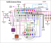
From the tear-down video, it appears that both solenoid wires are brought out in a wiring harness attached to a multipin connector mounted on the valve body. It should be possible to connect one wire to the +12 V DC automotive supply and the other wire to the drain of a power MOSFET. Things get a bit more complicated, but not excessively so, if further down the line one of these wires is permanently "grounded" to the auto chassis ground and the remaining wire must be driven with positive PWM pulses... Please let us know how you intend to drive the solenoids. Does your test rig substitute for the GM Power Train Control or ECM module? Will you need to read and process the speed sensor and throttle position sensor? Your original post indicates this is not necessary, at least for testing on a dyno, but it is probably a good idea to include this "feature" if you are going to the trouble of building a test set.
If I were driving the pressure control solenoid, with one side connected to +12 V DC automotive supply and the other "ground" side accessible for control, I would use a single n-channel enhancement-mode power MOSFET rated at least 2A and perhaps 30 to 60 VDC maximum Vds. It is problematical whether it is necessary to use expensive fast-switching Schottky diodes to clamp the inductive switching spikes. I have had good results with common 1N400x series power diodes. The low forward voltage drop and extremely fast reverse-recovery time of Schottky diodes is not needed, IMO, to protect the MOSFET switch from inductive transients that occur when the current in the solenoid is switched off. Be aware that a flyback protection diode connected in parallel with the coil will slow down the decay in current through the coil when the MOSFET switches off. This "slow down" effect limits the maximum frequency at which a PWM-controlled solenoid can be operated. This can be alleviated somewhat by placing a low-value resistor in series with the flyback protection diode. The resistor helps dissipate more quickly the energy stored in the magnetic field of the solenoid, said energy being otherwise dissipated in the solenoid wire resistance and the diode forward resistance, which if too small extends the current decay time. A second diode in parallel with the MOSFET drain and source terminals (cathode connected to drain) should be mounted as close as possible to the MOSFET and should not have a series resistor. Do not depend on the MOSFET "body diode" to perform this function unless the manufacturer's datasheet specifically states it is suitable for that purpose.
As to how to generate a continuously variable 5% to 40% duty-cycle pulses for the solenoid... you could use an Arduino for that, but it is probably not necessary unless you want the Arduino to do other things... like decode four shift buttons, light gear indication LEDs, and prevent dumb things like shifting from first gear directly to fourth gear... things like that are pretty easy to code in software and easy to make changes. For an analog circuit solution, a pair of 555 timers can generate your range of duty cycles, using a transistor to vary the pulse-width of one 555 operating as a monostable re-triggered by the second 555 running at 292.5 Hz. There are other analog circuits that can accomplish this too, such as the triangle-wave and comparator suggestion offered by
@Arouse1973 in post #3 above.
One problem I see is accommodating failure modes. What happens if the pressure solenoid fails to energize? Is there a mechanical pressure-relief valve that prevents overpressure of the hydraulic fluid? Do you need negative feedback control of the pressure from a hydraulic pressure sensor? Also, is there a shift-lever position sensor or switch that somehow overrides the two shift solenoids if you need the transmission to remain in a lower gear?
From what I have read so far, this is the best transmission ever made. How could GM possibly go bankrupt with engineering like that? Yeah, I know... bad management.
Hop