Hey everyone,
I have a nice project that the sole purpose is to control a servo w.o using a microcontroller.
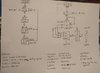
I have built a sort of PWM. I dont have an schematic, just a block diagram I can upload when I get my phone back.
I am using the Parallax Servo with range of 0.75ms to 2.25ms with the center at 1.5ms.
I determined that if I want 1 degree to correspond to 1 bit (more on this later) I would need a period of 8.33uS or ~120khz. So I simply put together an astable 555 timer (with a pot for Rb) to get my desired frequency. I do have a simple solder kit function generator, but I prefer having all my components on my breadboard.
I then use a 74hc161 counter (just one for now, will need 3 to get the minimum timing of 0.75ms)
and a 74ls181 (I wanted a quick one chip solution, bought some comparators though) to compare the counter with the desired pulse length. Or more straight forward: I use the comparator mode on the 74ls181 to determine when to reset the signal based on a value I can manually input into the 74ls181 through jumper wires (for now). The A=B pin will be my output to the servo as well as the the reset (through a NOT gate) to the 74hc161 counter.
This way I can change one bit on the 74ls181 and have it correspond to 8.33uS on the pulse width, which is equal to on degree on the Parallax Servo. By one bit I mean numerically one. Obviously the 2nd bit would equal 2 degrees or 16.66uS.
"Main Issue"
The only problem I have now is: how do I synchronize this clock with a 50hz clock? The servo requires a 20ms delay between pulses.
I have thought of having a 50hz 555 timer(CLK) to control the first 555 timer (PWM) via the reset pin. When the altered PWM goes high, the CLK should be halted by the reset pin.
On the falling edge of PWM (the altered frequency) could trigger CLK to start up again, but how could I be sure that the counter (74hc161) would be reset properly? The PWM is going at 120khz which is kind of fast for most breadboard projects I have done.
Is there some better way to do this?
The main point of this project is to learn, not really doing things "easy" or whatever. I could control a Servo in 2 minutes with an Arduino or BASIC STAMP.
So ask any questions if you do not understand what I said or need clarification!
I have a nice project that the sole purpose is to control a servo w.o using a microcontroller.
I have built a sort of PWM. I dont have an schematic, just a block diagram I can upload when I get my phone back.
I am using the Parallax Servo with range of 0.75ms to 2.25ms with the center at 1.5ms.
I determined that if I want 1 degree to correspond to 1 bit (more on this later) I would need a period of 8.33uS or ~120khz. So I simply put together an astable 555 timer (with a pot for Rb) to get my desired frequency. I do have a simple solder kit function generator, but I prefer having all my components on my breadboard.
I then use a 74hc161 counter (just one for now, will need 3 to get the minimum timing of 0.75ms)
and a 74ls181 (I wanted a quick one chip solution, bought some comparators though) to compare the counter with the desired pulse length. Or more straight forward: I use the comparator mode on the 74ls181 to determine when to reset the signal based on a value I can manually input into the 74ls181 through jumper wires (for now). The A=B pin will be my output to the servo as well as the the reset (through a NOT gate) to the 74hc161 counter.
This way I can change one bit on the 74ls181 and have it correspond to 8.33uS on the pulse width, which is equal to on degree on the Parallax Servo. By one bit I mean numerically one. Obviously the 2nd bit would equal 2 degrees or 16.66uS.
"Main Issue"
The only problem I have now is: how do I synchronize this clock with a 50hz clock? The servo requires a 20ms delay between pulses.
I have thought of having a 50hz 555 timer(CLK) to control the first 555 timer (PWM) via the reset pin. When the altered PWM goes high, the CLK should be halted by the reset pin.
On the falling edge of PWM (the altered frequency) could trigger CLK to start up again, but how could I be sure that the counter (74hc161) would be reset properly? The PWM is going at 120khz which is kind of fast for most breadboard projects I have done.
Is there some better way to do this?
The main point of this project is to learn, not really doing things "easy" or whatever. I could control a Servo in 2 minutes with an Arduino or BASIC STAMP.
So ask any questions if you do not understand what I said or need clarification!