I'm wanting to build a fan controller for multiple sets of fans. 5 groups of 4, and 1 group of 3. Each will have its own speed switch, with High/Med/Low. I don't need a pot for setting the speed, three set speeds is what I'm going for.
Right off the bat, I have a simple question, since Googling it doesn't seem to quite give me what I want.
All the PWM circuit diagrams for fans I can find only show one fan. Is there any issue with running multiple fans in parallel off of one transistor? They'll all be going the same speed.
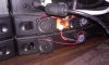
I've thought of two different ways I can set this up. First would be to have a separate 555 timer circuit with a selector switch for each group of fans. I have that drawn up in FIG 1. The two switches in the circuit are the same 2P3T switch. One side for the speed setting, and the other for the LED indicator. The part off in the box is already put together and running.
FIG 2 would be to have 3 timers running, one at 50% Duty cycle, one at 70%, and one at 90%. This would have a switch simply select which timer would be controlling the fans. This is just a diagram for concept, obviously no a complete diagram.
Which would be the best way to go? I'm thinking the second option would be simpler and smaller, but knowing the way my ideas go, there's some unforseen problem with this setup that I'm unaware of. Thanks in advance.


Right off the bat, I have a simple question, since Googling it doesn't seem to quite give me what I want.
All the PWM circuit diagrams for fans I can find only show one fan. Is there any issue with running multiple fans in parallel off of one transistor? They'll all be going the same speed.
I've thought of two different ways I can set this up. First would be to have a separate 555 timer circuit with a selector switch for each group of fans. I have that drawn up in FIG 1. The two switches in the circuit are the same 2P3T switch. One side for the speed setting, and the other for the LED indicator. The part off in the box is already put together and running.
FIG 2 would be to have 3 timers running, one at 50% Duty cycle, one at 70%, and one at 90%. This would have a switch simply select which timer would be controlling the fans. This is just a diagram for concept, obviously no a complete diagram.
Which would be the best way to go? I'm thinking the second option would be simpler and smaller, but knowing the way my ideas go, there's some unforseen problem with this setup that I'm unaware of. Thanks in advance.