I connect gate to no 10 ic leg and another mosfet gate to no 11 ic leg... For drain i wire to 0v trafo and another one also same to another 0v trafo... For source i jumper that two leg connect to -negative.. i think it same like a picture..
Maybe you connected the Mosfets and transformer wires backwards.
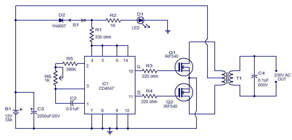
Nothing on the transformer connects to 0V except the metal frame. The drains of the Mosfets connect to the transformer outer 12V wires and the transformer center tap connects to +12V.
The sources of the Mosfets connect together and connect to 0V, there is no -negative.
With R5 at 390k and C2 at 0.01uF (sometimes marked 103) then the outputs pin10 and pin11 of the CD4047 turn on and off at 60Hz that looks like LEDs are continuously turned on or a multimeter shows a continuous voltage. Use 470k for R5 for 50Hz.
To see LEDs turn on and off alternating then replace C2 with 0.22uF (marked 224) but the frequency will be 2.7Hz which is too low to drive a transformer.
When pin10 of the CD4047 goes to +12V then its Mosfet turns on and its drain goes to 0V. When pin 10 goes to 0V then its Mosfet turns off and its drain goes to +24V. Pin 11 and its Mosfet do the opposite so at any moment only one Mosfet is turned on.
This is a high power inverter that
cannot use a low current breadboard and small 20awg wires. Maybe your transformer is too small to make 50Hz power and is not 24V center-tapped (12V-0-12V).