Maker Pro
Maker Pro

problem in 12v - 230v inverter

hello,
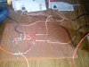
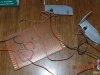
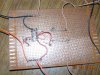
i have made an inverter using cd4047 as per the circuit diagram i have uploaded here.. as per the circuit diagram gate pulse are given to the mosfet from pin 10 and pin 11 of the IC . but when i apply 12v to the ic i am getting 12v at pin 10 but not getting any voltage at pin 11 but i am getting 12v from pin 13 so i have connected 100ohm resistor to pin13 . but still i am not getting output from the transformer. i am using a 12-0-12v to 230v center tapped 1.5amp transformer. please tell me where is the fault in my circuit?
 

Attachments

  • 12vdc-220vac-inverter.jpg
    12vdc-220vac-inverter.jpg
    26.9 KB · Views: 131
I'm not aware of any forum etiquette that does not frown on duplicate posts.
You have posted this exact post 3 times intentionally in different sections of the forum. If you are not sure where to put it, please leave it in one spot and openly ask it to be moved if it's in the wrong spot.

Pin 13 is not on the diagram you posted. Assuming that diagram is correct, have you double-checked your connections?
Can you provide any pictures of your circuit? (Please include part numbers)
 
in this diagram pin13 is unused pin which i have checked it is having 12v supply and pin11 is not having 12v supply so i just interchanged the pin connection from pin11 to pin13 to trigger the mosfet.
 
Pins 10 and 11 will vary and alternate to generate your output... using pin13 just because it has 12V on it is not a good reason to change the circuit.
If pins 10 and 11 are not changing, then something is wrong with the circuit. Double-check your connections and post a clear picture with the component numbers for us to take a look.
 

KrisBlueNZ

Sadly passed away in 2015
Gryd3, thank you for flagging those duplicate threads with a link to the most appropriate copy (this one).

devmania, a few seconds' thought should have been enough to tell you that posting the same question to multiple threads would only lead to multiple mixed-up replies and an enormous waste of time for the volunteers who are trying to help you. In general, you should try to spend those few seconds.
 
ok i will check it once again and i will connect the component according to the circuit diagram. lets hope my circuit will work and i will upload photo of it also
 
i have checked it once again.. but still the problem persists
 

Attachments

  • IMG_20140928_124216.jpg
    IMG_20140928_124216.jpg
    184.5 KB · Views: 143
  • IMG_20140928_124010.jpg
    IMG_20140928_124010.jpg
    147 KB · Views: 118
  • IMG_20140928_123844.jpg
    IMG_20140928_123844.jpg
    195.6 KB · Views: 141
may be this photos will give clear idea about the construction
 

Attachments

  • 1st.jpg
    1st.jpg
    251.5 KB · Views: 119
  • 2nd.jpg
    2nd.jpg
    297.1 KB · Views: 148
  • 3rd.jpg
    3rd.jpg
    253.3 KB · Views: 117

KrisBlueNZ

Sadly passed away in 2015
No they don't. Have a look at those photos and see if you can tell which pins of the IC are connected to what. I can't. The second one also has a reflection from a flash which obscures a lot of the board.

Read those two resources, try again, and check your pictures before you upload them.

You may need to borrow a better quality camera.
 
hello sir,
please download the photo and zoom it. i have mentioned every thing on the photo..
 

Attachments

  • 1stnew.jpg
    1stnew.jpg
    253.9 KB · Views: 116

KrisBlueNZ

Sadly passed away in 2015
It's still too small to see clearly.

Try taking a close-up of the used part of the circuit board.

Also while you're at it, join those heatsinks together with some nylon nuts and bolts. They're just an accident waiting to happen.
 
We need the picture so that we can see if there are dry joints, shorts, etc. in addition to proper wiring.
If the pictures are not clear enough to determine this, they are more or less useless.

Read the resources linked above regarding taking photos. (thanks Kris for correcting mine)
Turn your flash OFF and take the pictures in decent lighting so there is no glare. Head-on, to minimize the obstruction caused by other parts on the board, and to provide a nice square image.
If you are getting blurry photos, keep still, or change the mode of your camera to Macro. If this fails, you may need to take the picture slightly further back. It does help to crop the image afterwards, as the forum only allows images to a certain size, and cropping it will increase the size of the actual board we want to see while cutting the garbage from the edges we don't need.

After you upload your photo, open it in the forums to see if it is still clear enough! Looking at the original wont cut it, as the picture is probably at least a 5-6MP image, where it is just reaching 1MP here on the forums.
 
Top