What? Are you asking whether it works? I haven't built it up so I can't say for sure, but I'm certainly expecting it to work!
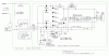
That depends on how you want to control the triac. For my project, I decided that you would be able to select from several different fan turn-off delays by switching the wall switch ON and OFF one or more extra times before leaving it to do its thing. It would have required a lot of discrete logic to implement that feature, so I decided to use a microcontroller. I also designed a version that doesn't use a microcontroller, and provides a single time delay, but it has three ICs instead of just one.
Well, you could replace D1~9 and Q1 with bigger devices, yes. This diode looks suitable:
http://www.digikey.com/product-detail/en/BYV79E-200,127/568-3440-ND and this triac:
http://www.digikey.com/product-detail/en/BT139-600,127/568-3665-5-ND
What is the load you want to control, and how do you want to control it?
") and its connect to 2200watt pump for water pumping. so i havent micro controller and i want the power for 2 mode 1.loade is off 2.load is on. the mode 1 is easy . and your suggest is good for time load is on(mode 2) and i prefer do not use micro and programming. whats 3 ICs you talking about? op amp and so on?
and its connect to 2200watt pump for water pumping. so i havent micro controller and i want the power for 2 mode 1.loade is off 2.load is on. the mode 1 is easy . and your suggest is good for time load is on(mode 2) and i prefer do not use micro and programming. whats 3 ICs you talking about? op amp and so on?