Maker Pro
Maker Pro

Power Supply Loading

I have two Black & Decker #9821 power adapters that I plan on using for power supplies for a slot car track that I'm building for my grandkids. They are adjustable output, min (?) to max 16v, 4 amp. However, when I check the output with my meter (with no load) I only get 13-14 volts over the full range of the adjustment. I'm thinking that I need to have a load on the output in order to get a true reading. Now my question. What type of load and where does it need to be? In series with the output or across it. The slot cars don't have near the loading that the power adapter tools did. I don't have any of the tools to try in the adapter. !B+tWiuQBmk~$(KGrHqV,!l0Ez+5CvKBrBN!hgon9i!~~0_3.JPG

432088175_tp.jpg
 

davenn

Moderator
hi welcome to the forums :)

even with no load you should still get a variation in the output.

The real question is ... is the PSU a variable voltage output or a variable current output ?
There are no info markings on the side near the adj. knob. the top label doesnt state anything about it being an adjustable supply which is unusual.

But assuming that it is an adj voltage supply. and the O/P isnt changing, that it has to be assumed that the adjustable voltage regulator has failed.

Open it up and do some sharp close up pics of the insides and lets see what's in there :)

cheers
Dave
 
Can't take pictures right now, at work. But, the transformer has this on it: 120 V AC, 60 Hz,
K.W. 29/84. There is a large heatsink (2.5" X 2.5") with a bridge rectifier and a transistor on it. The bridge rectifier looks like this:bridge.jpg ,with Fagor B 40/35-10 written on it. Output from xformer is connected to the bridge rect. The neg. conn. on the bridge goes to ground on the board and the pos. conn. goes to the middle leg of the transistor and to the pos. side of a capacitor on the board. There are several small resistors on the board and a potentiometer (that I haven't measured yet) I don't think that the regulator is malfunctioning because all three of them (I have an extra one) are performing identical.
 
A power tool adapter probably outputs a constant 12 or 14VDC.
The adjustment would be for very minor voltage adjustment near that voltage.
(Not a 0 to 14VDC range)
Typically, unloaded outputs would read a little higher than 'normal' (loaded) voltage.
When you put your load on the output, you should go to the 12 or 14VDC you'd expect.
If you've got a 12VDC car light bulb, you could use that as a load, to measure your
loaded voltage on the adapter output.
 
OK. I'll try the light bulb. But, I really want this to work as an adjustable power supply:D. The user manual that came with it explains about using the assorted tools. One of them is a rotary tool (similar to a dremel) and it states that the control knob will change the speed from 6,000 rpm to 30,000 rpm but will NOT reduce it to a stopped condition. Is there a way that I can make it more adjustable (change the pot.?) say from 0 to 12 volts.
 
i tried the light bulb using a 12 volt headlight. Output varies from 11.99 to 13.3 volts. i measured the pot.= 100K. I'm trying to draw the schematic based on circuit board connections.
 
slot car power supply

Hi there Lejoy.
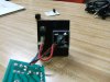
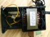
What you have there looks like a contender for a good slot car power supply.
Not sure what the red button is, reset or something like that, or charge start ?.
Any way the easiest way is to modify your psu for the job.

I very much doubt the full exciting circuit can be modded for 0 - 14 volts DC.
You could keep the bridge rectifier, and maybe use the filter capacitors, although motors of the permanent magnet type are not fussy on some out put ripple.

I would use a regulator circuit to power the cars, most wont go down to 0 volts DC , but they will drop to 2.5 volts or less, this wont move a 12 volt DC slot car, so is as good as 0 volts DC, when not powered the supply would be loaded at 2.5 volts or less, but the small motor windings will only draw a modest current, this is fine on the supply and the cars, until you turn up the voltage and power up the cars.

For control i would opt for a slider potentiometer as opposed to a rotary one, it would be more practical, although either will work.

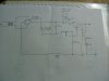
A voltage regulator circuit can be found on the web, there are many, some easy some more complex depending on the final use, if it where me i would build a small circuit on copper strip board and mount inside the box unit.

Really i doubt the existing circuit will ever take you to 0 volts and back up to 14 volts.

there is a kit available from transformer to out put posts circuit, its relatively cheap, but only supplys 1 amp, you can replace the diodes for the rectifier with larger current ones, and use a 5 amp IC regulator in place of the kit one.
I will list the parts to replace in the kit to get higher current.

Vellman Kit is K1823, replace LM317 IC Regulator with an LM338T and change diodes to 1N5408 rectifier diodes the diodes will limit the power to 3 amps, but at a squeeze 6 amp diodes will fit, 6A10, either set of 4 diodes are a direct replacement for the 1 amp diodes in the kit, 1N4007. As is the voltage regulator, 3 amps for slot cars should be fine, and replace the horizontal preset potentiometer with an off the board rotary or sliding potentiometer of 4.7K oh on a final note the kit is available in most parts of the world.

I only suggested a kit configuration as it will uncomplicate things if you build a variable voltage regulator circuit, but if you want you can build a custom one from scratch, its up to you, but the units look like an ideal slot car psu contender.
Dave. :)
PS, The replacement parts are available at all good electronic retail stockists, or on the kit link site, under components as a PDF file of there components catalouge, but other electronic stores sell all the above including the kit.

http://www.esr.co.uk/velleman/products/index_kit.htm
 
Last edited:
I would like to keep things as simple as possible and change only the components that would be necessary. I will have a meter on both units. I'd like to be able to go up to 12 volts. Minimum is no problem as long as I can get to below 6 volts. Current limit of 2 amps would be fine since each lane will have it's own power supply. I was able to get some pictures of the inner workings of the units. I'm trying to freehand a schematic based on visualization of the board. The bridge rect has this written on it: FAGOR B 40/35-10. The transistor (regulator?) has this written on it:628 400 TAG 8434. The large capacitor is 220 microfarad, 16V. The potentiometer is 100K ohm. Transformer output is: 18volts (disconnected, no load). What components do I need to change in order to satisfy my wants?
 

Attachments

  • DSCF0623.jpg
    DSCF0623.jpg
    145 KB · Views: 222
  • DSCF0626.jpg
    DSCF0626.jpg
    146.3 KB · Views: 214
  • DSCF0631.jpg
    DSCF0631.jpg
    149 KB · Views: 245
  • DSCF0636.jpg
    DSCF0636.jpg
    141.6 KB · Views: 272
  • DSCF0639.jpg
    DSCF0639.jpg
    139.5 KB · Views: 253
  • DSCF0643.jpg
    DSCF0643.jpg
    147.7 KB · Views: 230
  • DSCF0644.jpg
    DSCF0644.jpg
    148.2 KB · Views: 355
Last edited:
I found this schematic of a variable power supply with adjustable voltage and current outputs.

L200var.gif

Will this work for my project and where can I find the L200 regulator? Would there be a better choice than the L200 for my application? What would be the drawbacks of this psu?:confused:
 
Slot car psu

The L200 is ok, but there are better, or more tougher regulators. Look up the LM338K, and current limit with a fuse in the unit. As for modding the existing circuit i doubt it very much, there are many good circuits on the net. I only mentioned the kit as its quick and will get you racing faster, but a custom circuits just as good, the L200 is a good regulator. Really its personal choice. Good luck with the modding, and happy racing, got to get into that soon with my son soon, bit young yet.
Dave.
 
Thank you so much for the info, davelectronic. I think I've decided to go with the LM338T as it would mount in the same place as the existing one. Can I solder directly to the leads without harming it or should I utilize a socket? I'll use an off board pot of 4.7K. Will the other components in the schematic be of the correct value to give me around 12 volts max down to somewhere below 4 volts with at least 2 amps? Also, what power rating should the pot be? And, will a 5K pot do the job? They are much cheaper than the 4.7K.
 
Last edited:
Yes you can solder to the regulator pins, but bolt it to a heat sink for this process, any heat sink is fine, does not need to be the one in the psu, if your soldering outside the box.

And a 5K Linear potentiometer is fine, the power ratings for this use are low 0.2 watts is typical, or what you have available, its only over here in the UK that are 5K Equivalent is 4K7.

I must say if your using the existing circuit with the LM338T it might not give the voltage range your looking for, as the existing circuit is designed for a power tool and not a wide voltage differential, also do some research on the component your removing, as device pin outs vary from each other, this will save time and grief.

Good luck with the modding, i am always modding stuff, and happy racing with your grandson.
Dave. :)
 
OK, thanks. The only components that I'll be reusing are the case, transformer and bridge rect. I'll etch a new board and use new caps and resistors.. The circuit component values I was talking about using is not from the hand drawn schematic, but the one I found online with the L200. How does this circuit look to you? It says input should be greater than 28 volts for an output of 32, but, my xfmr out is only 18V. Problem, or not?
http://www.national.com/mpf/LM/LM338.html#Overview
 
Last edited:
RC cars

What your going to build on a new pcb is fine, the voltage you mention is fairly much the maximum, 3 - 4 volts above your top out put volts is fine, the voltage output on 18 volts input, this should be about 15 or close to that. If the input is 18 volts before rectification and filtering it will be a bit more. Test the out put with a meter before racing, but i cant see a problem, for better performance i would use a 4700uf as a main filter cap, and 470uf on the final output, to avoid line load drops.
Dave.
 
Slot cars

No worry's mate, yes enjoy the modding, and Racing, hope it all works out ok, cant see no problems.

have fun with it, and the racing with your grandson.
Dave.
 
OK. I've built my power supply using this schematic with some changes.View attachment 00906001.pdf
Voltage in=18v, C1=4700 microfarads, C2=470 microfarads.
Works great!
Question. How can I limit the output to 12 volts? Do I need to change R1? If so, to what value?
 
Ive not limited theLM338K to 12 volts before, R1 sets the reference voltage to 2.5 volts the potentiometer varys the output, you cant really add more resistance with out affecting current, i am not totaly sure on the best idea, diodes drop volts, but thats to much for diodes. The only thing i would do is change the transformer, or remove windings on the secondary to close the voltage differential, other members might know of a way i dont as yet.
 
Top