Maker Pro
Maker Pro

Pioneer S-W700 Subwoofer

I have been troubleshooting the Pioneer S-W700 sub woofer for sometime now off and on. I have replaced several components on the Power Mod. F100, board #AWZ5389 board. The board has some foil raised near the right channel output transistors. Foil completely off and copper trace exposed. I would like to find a replacement board for this unit. Does anyone have any idea where I might start looking? Pioneer does not make the parts anymore. My only resource is to find someone who has this unit and would like to sell it for parts.

Any other suggestions? I have attached a picture of the backside(foil side) of the board. Would appreciate any thoughts on how to proceed.
 
I keep old transformers, motors and inductors for the magnet wire (enamel wire) for this very purpose.
Even single strands from stranded copper wire works fine but is not insulated. So careful bending and maybe glueing is required. Easy to do but takes patience and is worth it IMHO.


Martin
 
I have attached a picture of the backside(foil side) of the board.
I think that it fell off the wagon and didn't ever make it here.

Any chance that it is being this specific power buss on either of its channels, if so you are not the SOLE person encountering this dilemma.
Its literally shouting at you . . . .to look at the direction of incoming power flow , and the Cu foil is damaged all the way down to ending at DEAD SHORTED PARTS.

Pioneer-SW-700-Power-Buss.png
 
Last edited:
Ok. Everything back together. Took it off my test current limiter( 100 watt incandescant bulb). Plugged directly to 110 power. Unit comes on,fan stays on all the time, and no output from the the speakers.
 
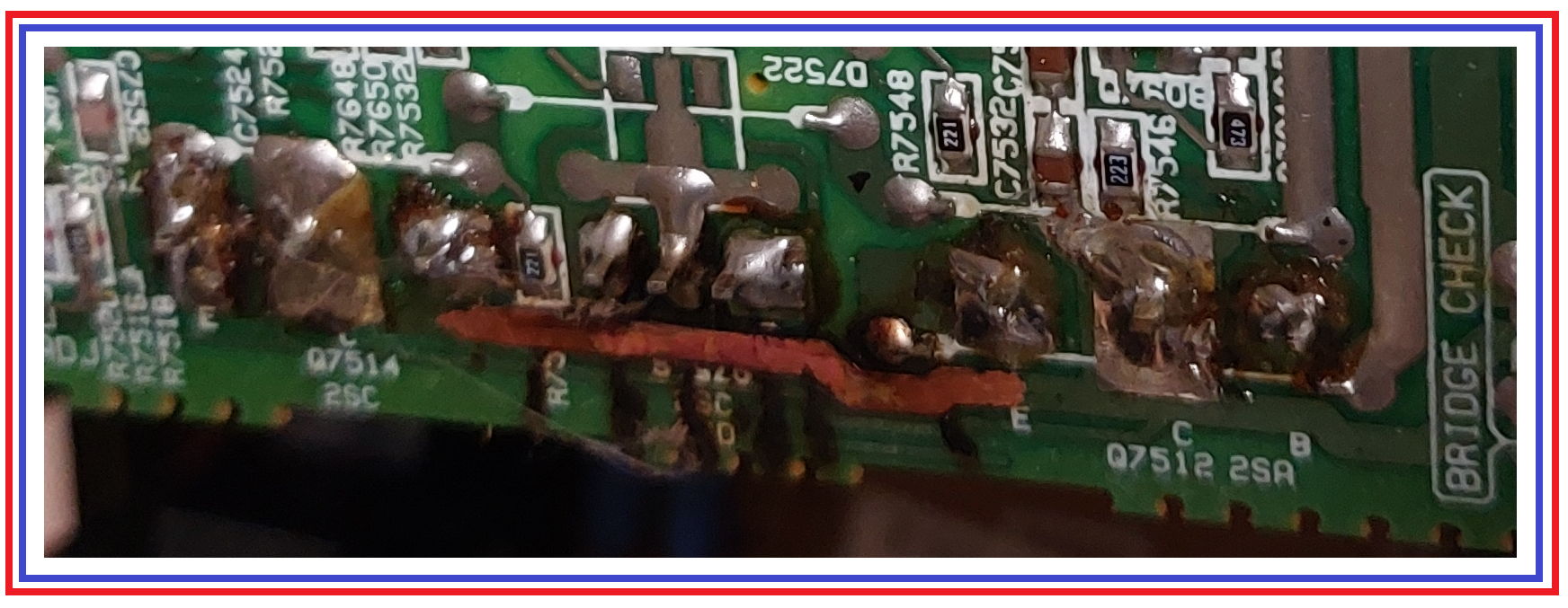
There are no replacement boards. How can I repair the copper foil on this board? The damage runs al the way from in front of Q7512 emiiter to in front of the collector of Q7514.
 
Sir coastman49 . . . . .

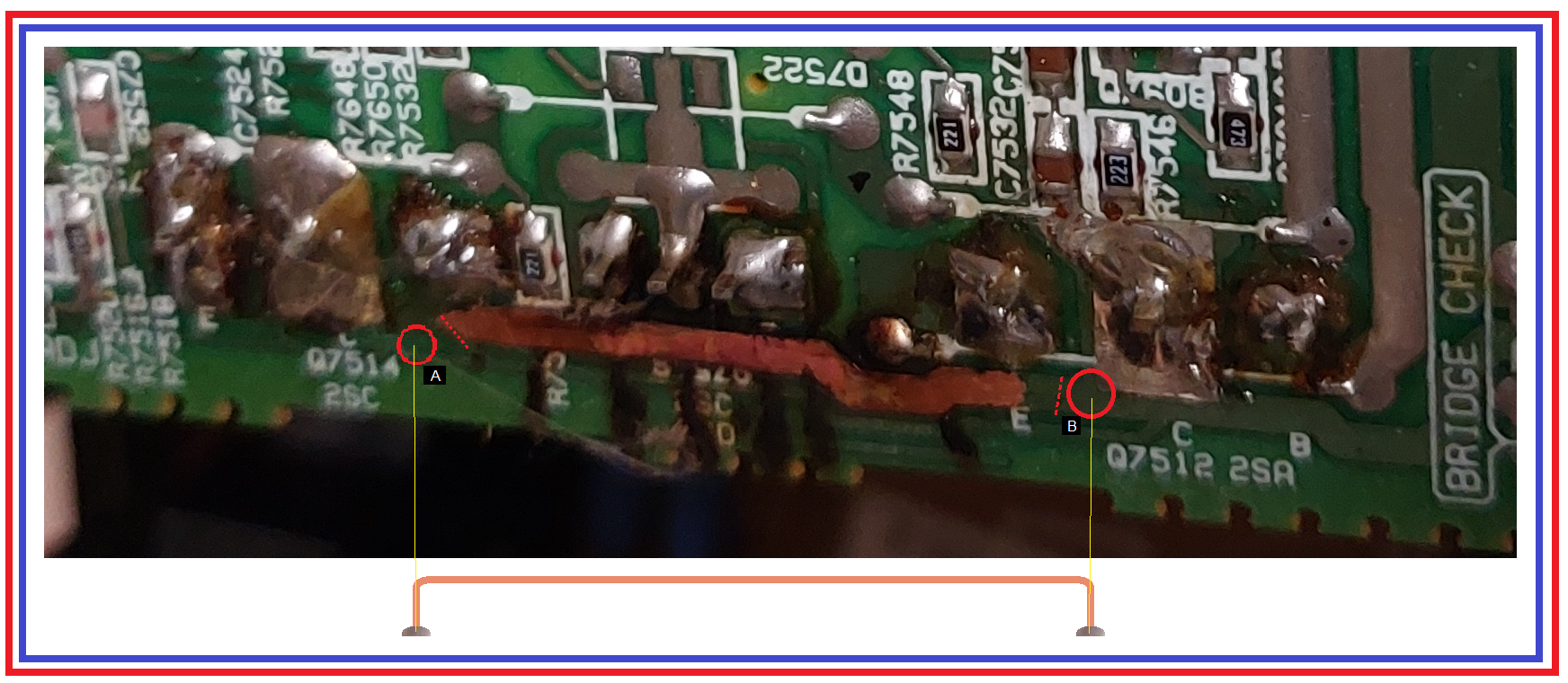
HERE . . . . . . is the way that I would enact a CLEAN / QUALITY / NOTEWORTHY repair of your boards now dismal situation / appearance .

Isn't it strange that I came up with the same photo / board condition that you described ?

You have the EYES on the board . . . . the best definition that this pic shows . . . . is being my eyes on the board.
Correct for accordingly, if required. . . . .

I see the originating DC power input at the BLACK square B / BRIDGE CHECK source and flowing down to feed a Q7512 PNP POWER OUTPUT transistor, and all is well up to that point, but the foil surface passing to the left all the way down to the BLACK A areas has annealed and lost temper, all the length of that path up to the Q7514 NPN POWER OUTPUT Transistor .
( Found it reading about 000.0 ohms in its C - E didn't you ?)
Go to the BLACK A and B areas and find some original, still pristine, quasi tempered foil such that you can scrape off all green resist an create the two RED circles. Flip the board horizontal to be able to rosin flux and pre solder / tin those two areas.
Look at the two RED dotted cut lines and deep score with a #11 Exacto knifes blade and peel up the now deeeeefunct foil between RED dotted line ends.

Get the required length of bare 10 ga solid copper wire to make the Cu jumper depicted.
Its sold by the foot or can be stripped out of Romex as one of its 3 conductors from Home Depot or Lowes or a working electricians stock.
I would only downgrade sizing / ga to no less than 12 ga.


Take spacing dimensions and replicate the arrow straight copper link with tight . . . right angle . . .end bends made around a 1/8 in rod.
Check for a fit to the created solder pads. Pre tin the copper wire jumpers lead ends.
Position the jumper as rising up vertically from the board . . . . standing off upwards with its two leads..
Go back to the horizontal positioned board and reflow solder connections at each pad using the provided gravity assist, and centrally holding the Cu link with a wooden clothes pin.
( HOT-sy totsy).

If done right, and neatly you should have now accomplished a quite noteworthy repair.
With this new link NEVER accruing any overload damage.
I can't see to confirm, but if there was being any interconnect to that central transistor to the burnt original foil buss. Two jumpers would be needed, vice the single one shown.. Duuuuuuhhhhhhhhh.

PICK-CHOOR . . . . .
https://i.ibb.co/7v0fSHX/Circuit-board-repair-link.png


Circuit-board-repair-link.png


and no output from the the speakers.
Not even on your non fried left channel ?
I will research that units schematic . . . .

73's de Edd . . . . .

A long drag on a pipe gives a wise man time to rapidly think on an imposed preponderance. . . . . . but for a mere fool . . . . . it's just being something else to put in his mouth.

.
 
Thank you so much for your insight. I am going to locate the copper wire and do the repair as you illustrated. No there was no output from the sub at all. I purchased a new coaxial cable and verified its condition whit a working subwoofer.
I will double check the Q7514 C-E resistance as well before starting the repair just to verify. Will let you know.
 
Last edited:
Not much surface area after I made the cut. Only a small solder pad to work with. 10 AWG pretty stiff. Can I go from connector to connector solder pads of Q7512 to Q7524? The foil runs from collector to collector.

Tinned and soldered the copper link from collector to collector solder pads of Q7512 and Q7514. Powered back on with current limiter test bed first. Light dimes and fan stays on just like before. Will try hooking to a receiver to see if I can get some output.
 
Last edited:
Ok. May have found another issue. Cable and connector CN-7502 is a problem. Wires to the R and L out, Ground ref. and B1+ were all broken. Could be the reason why no sound output. Moving the pc board often while I have been trying to repair it, may have caused the cable to break. It broke right at the connector. Problem for me is how to repair it. I don't want ot take the connector of the board. It is soldered with small solder pads. Is it possible to cut the cable and reconnect it? I am uploading a pic.
 

Attachments

  • 20220525_2152321.jpg
    20220525_2152321.jpg
    58.2 KB · Views: 2
Sir coastman49 . . . . .

O.K. . . .then . . .here is how I would take care of that situation in a professional; appearing rework / repair.

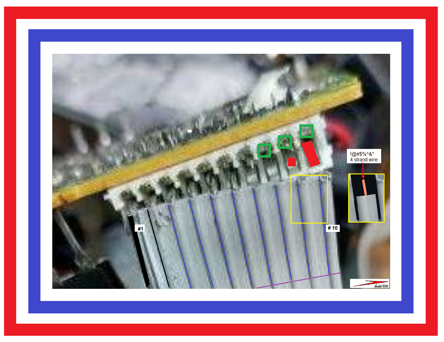
That specific funky gray ribbon cable that uses about 4 strands of #26 wire to make a stranded wire, has about a 6 time flex factor and then it breaks off.

Note the partial marking of the GREEN square areas where the wire was originally circularly clamped / crimped.
Pull the cable and use micro cutters to get rid of all of each clip remnant as is possible.
CATCH ALL the flying deteris in a cloth ! . . .No wantee floating shortee -shortie chips in board circuitry.
The pin 10 RED markup is the contact that is to be the new contact area, but, back up to pin 9 to see,JUST the small RED end area, that to be used for each new SOLDER drop tinned connection.
Look at the YELLOW SQUARE cable inset to see the slicing down the DEAD center between each wire BLUE LINES , of such distance down, PURPLE CROSS LINE, such that individual wires can then be easily manipulated into rework positions.

A jewelers standard screwdriver (scraper) from a $ Dollar Store $ set of 6 does a good job of cleaning all of those RED square areas prior to placing a drop of rosin flux and using a fine soldering iron tip to add wire flux solder and TIN all 10 connections.
Alternate from one end connector of the board to the other end to keep heat from amassing /concentrating.
Then rosin flux and pre tin those prepped new wire ends.
Then start at an end and start placing in one wire at a time, appreciating the flexibility / manipulation , afforded by having split the webbing.
Finish up and do TESTEE-TESTEE. . . . . . . . . . . ( ITS ALIVE ! )

CONNECTOR REPAIR . . . . .
Ribbon-Cable-Repair.png

https://i.ibb.co/tZW2LWD/Ribbon-Cable-Repair.png


Tha a a a a a a a a a a a sit . . . . . .


73's Edd . . . . .

Always listen to experts. They'll tell what can't be done and why. Then do it.


.
 
Last edited:
Before I got your post, I went ahead and removed the connector. So should I now make the repairs before reinstalling the connector? I guess that may be easier. I will attempt your repair suggestion tomorrow. Will let you know how it turns out.
 
Repaired the cable per your instructions. Checked to make sure there were no loose strands. Plugged back into my light bulb test circuit. Bulb still bright, indicating an issue somewhere.
 
Sir coastman49 . . . . .

Initially, just want to confirm that your test lamp is being an OLD SCHOOL filament-incandescent lamp . . . . not a newer CFL or LED family of unit .A RE-READ CONFIRMED . . . .INCANDESCENT.

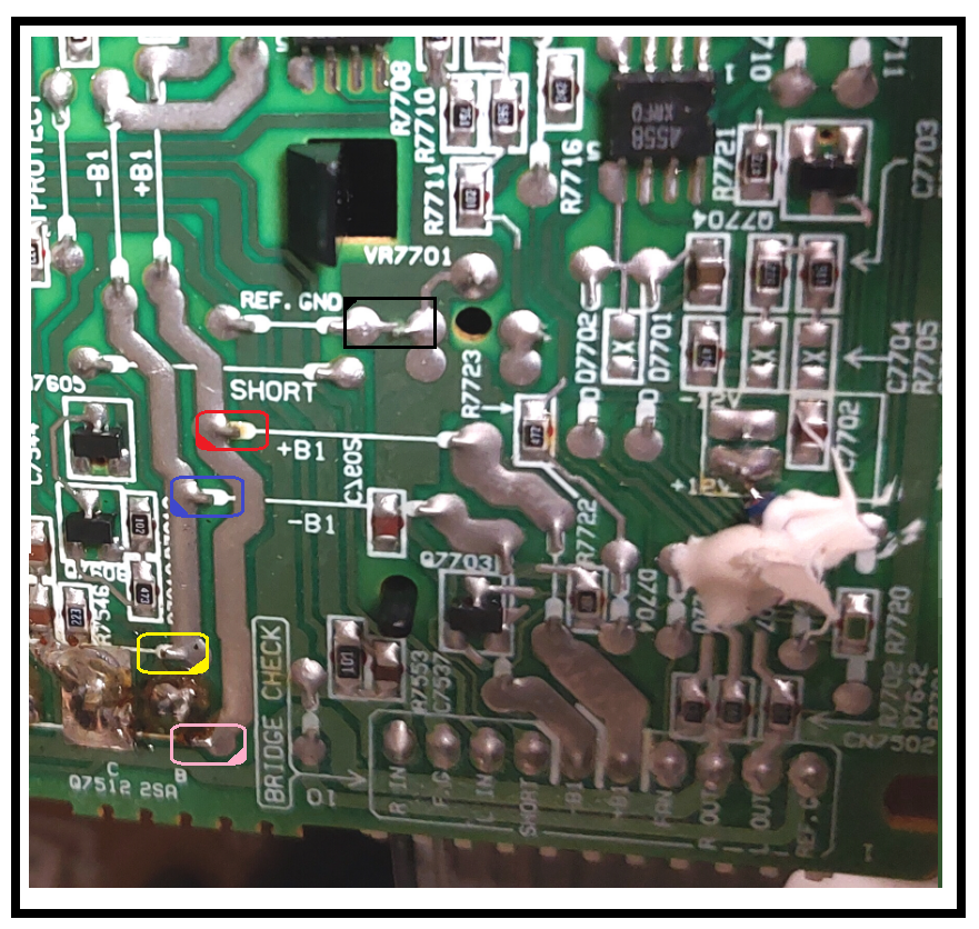
Is this board shot photo being in agreement with your board . . . . specifically my marked in BLACK RECTANGLE common ground connection and then the RED RECTANGLE for a B+ voltage and BLUE RECTANGLE for a B - voltage .

BOARD SHOT . . . . .

Pioneer-SW700-Trace-Shot.png


On a proper operating unit expect + and - 50'ish volts on those supplies . . . . with your limiting provided by the test lamp . . . we will just have to wait and see what voltages you will read.
But I would expect the voltage pairs to be the same . . . . or there is a serious overload / short on that lines, interconnected power components.
In order to be able to only power up the unit for JUST long enough to take voltage measurements . . . one at a time.
Temporarily tack solder a bare wire to each BLACK -RED -BLUE test point, so that you can then clip lead connections to your meter probes.
Then power up . . two separate times . . . just long enough to be able to get those + and - voltage supply readings.

Jumping ahead . . . . if imbalanced / low voltages were found . . . next step would be to go to YELLOW and PINK rectangles . Straighten up those jumper wire ends and push thru board, so that they then will disconnect and are floating on those end(s).
Retest and see if the RED and BLUE supply voltages came up . . . . . or / now part of your unit might actually be working .

Standing by for findings . . .

73's de Edd . . . . .


Some come to the fountain of knowledge to drink . . . . . while others just gargle.


.
 
Last edited:
Ok did the test. Got -.04 volts on the -B1 and .043 volts on the +B1. Saw a little smoke when I first did the +B1 but no blown fuses. Lifted the jumpers. Tried to make the measurements. Getting smoke near the power rectifier. Looks like coming from the big capacitors..
Do you know where I could get this board, the power output board? I have been surfing the electronics forus but no luck yet. I am afraid this board has reached its limits as well as me.lol.
 
Sir coastman49 . . . . .

I wonder how many fuses were put in that unit until it finally melted down to this current state of disrepair ? . . . Are you fully familiar with that history ?.

I can see an INITIAL core failure, of probably just 1 of 4 power transistors that are in the audio power output stages of that unit.
Irregardless of all of its protection / overload/ short / over voltage / over current circuitry.
Now, along comes a replacement fuse and a waiting for (11 teen [ Lebenteen] / 1000ths) of a second . . .POW . . . there goes, potentially another / or more output transistors .
Then comes another fuse ( suspicioning . . . that last one was probably being a BAD fuse ) o_O
STA A A A A A N D . . . .back here comes another fuse . . . . after all, there are 5 packaged in a box !
This time in the central core power unit . . . the D1201 Full Wave Bridge Rectifier block shorts down . . . another fuse gone . . . alas . . .no joy .
Well one to go . . . . . POWER UP . . . . . Hm m m m m m m m m . . . I wonder why that 1 1/2 inch length of circuit foil is glowing a dull cherry red ?

Am I . . . PRECISELY . . . all up to date now ?

TRUISM . . . . .
The use of a 60-100 watt incandescent lamp, subbed in circuit for the fuse should be employed, initially, just after encountering a blown fuse.
NOT after sequentially blowing other fuses.
" Mouth to mouth doesn't revive a dead cadaver ".

upload_2022-6-1_5-41-45.png


I think that you now have 1 or more shorted power transistors of its 4 and the Full Wave Bridge Rectifier block is damaged . . in 1 x . . .2x or full 4 x of its sections..
AND . . at no extra charge . . .potentially the 2 . . .R1205 and R1206 resistors from the +- 50 VDC supplies to the main ground buss, are now being open circuit..

Considering that you will start with an unplugged , dead stone cold set from overnight inactivity, find the HUGE E-caps C1201 and C1202 and read the DC voltage across them. If any voltage is still present short it out. Then go to lowest ohms range and see if any short or low ohmmage is being read across their terminals.

Take your meter and put in low ohms range an short its probes together to see its meter reading .

Using the schematic below find the D1201 Rectifier block and pull it out of circuit and test its 4 diodes in low ohms resistance mode initially
Then go to diode test mode and see of being infinite in one directuion and reading the forward diode voltage ofg that diode in the other polarity in the testing each of its individual diode.
Expecting 1 or more shorted units.
Then go low ohms and see if see R1205 and R1206 might have opened up from overload.

D1206 . . . .it's a looka like 'a dis . . .
images


https://encrypted-tbn0.gstatic.com/...SuXURbVIvPrNDlj68Q_2etYpYD7319deiHW8&usqp=CAU

Lastly, you can test across the 4 POWER audio output transistors from their Collector to Emitters for any shorts or low ohms readings.
Likely SUSPECTING the 2 transistors near your former HOT foil area.

Waiting for results / or / any procedural assistance ? ?'s.

73's de Edd . . . . . . .


Be content with what you've got . . . . . but just first . . . . . initially be sure that you've got plenty.


.
 
Will pull the rectifier later today. Looks like Q7511, Q7512, Q7513, Q7514s all have Emitter to collector resistance readings near zero, like 0.05 ohms etc. I just replaced al 4 of them about two weeks ago. Don't have good faith in this board.
 
Top