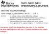
The datasheet clearly says the max allowed input voltage is +/- 15V or the supply voltages.
What value is your input resistor to ground?
Please post your schematic.
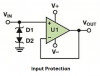
I forgot. You probably do not need RS because the current from a piezo transducer is very small. The input of the opamp must be biased with a resistor to ground if you have +/- supplies. This resistor is the load for the piezo and it determines the highest voltage produced when the piezo is hit hard.
It's a whole bunch of different cv ins on the synth modules. It might be that I just need to standardise them or have a switchable option. Here's the chematic from MFOS VCA.
The first opamp in the VCA is a mixer with an input impedance fairly low for a piezo transducer of 100k ohms and no gain. The output of this opamp is 1/50th the input level. It feeds either a pair of Mickey Mouse log transistors (affected by temperature) or a linear opamp with a voltage gain of 50.
The first opamp in the VCA is a mixer with an input impedance fairly low for a piezo transducer of 100k ohms and no gain. The output of this opamp is 1/50th the input level. It feeds either a pair of Mickey Mouse log transistors (affected by temperature) or a linear opamp with a voltage gain of 50.
So i folllow the voltage path see what active components it hits alo the way and make sure it stays within their tolerence lvls? that would be both transistors u1c/d lm13700n pins 1,5 and 7.
My signal is coming in at potentially 11 times gain, then added to u1d's x50 gain seems rather too much,