Maker Pro
Maker Pro

PIC A/D question

Hi,
I am looking to use a PIC A/D channel, the PIC is PICLF1936. I have used a forward biased diode connected with a 1K resistor to measure temperature, every 2mV gives a degree change.
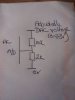
I am trying to implement the same with a voltage divider. The network set to 500mV, using a 10k (source resistor) and 2K connected to 0V. The source voltage being adjusted from a DAC. Set to 3.3V. Is there any thing that I might have missed, in particular A/D impedance if PIC etc.
Thanks in advance.
Rajinder
 
Do you have a circuit diagram you can post here. Everything sounds ok and the data sheet will tell you the max input resistance recommended. This does depend on the time required to make the reading. It the resistance is too high and you are sampling too quickly you may get inaccurate readings.
Thanks
Adam
Hi Adam,
Will upload one asap.
Thanks for your reply.
Best regards,
Rajinder
 
Hi Adam,
Sorry for the delay in getting back. I have attached a circuit diagram. The Output voltage from the DAC will be adjusted 0-3.0V. The voltage from the potential divider fed into the A/D channel of the PIC. The voltage divider gives 500mV. I need this to be between 500mV to 640mV. I know the PIC source impedance is 10K max but not sure on impedance looking in from the 2K resistor side. Can you clear a point out for me too. For example if the A/D channel has a input impedance if 20K, does that mean I need something greater than this so it doesn't load the voltage I'm looking at this from a potential divider, if I have 2 x 10K potential divider, then if I wanted to put a load across the bottom resistor it needs to be at least x10 greater I.e. 100K. Is this the same with impedances?
I look forward to hearing from you.
Best regards,
Rajinder
 
Let me upload again, sorry.
Here it is.
Best regards,
Rajinder
 

Attachments

  • IMG_20160306_190540257.jpg
    IMG_20160306_190540257.jpg
    125.8 KB · Views: 86

Harald Kapp

Moderator
Moderator
@Rajinder : Please remember to always include a circuit diagram in your posts from the start. Do not let us ask for one every time. While it may look simple and easy for you to understand your verbal explanations - remember that we do not have the comfort of looking at your circuit and have a hard time imagining what you are talking about.
As the saying goes: "a picture is worth a thousand words".
 
Top