Maker Pro
Maker Pro

PCB for Dishwasher repair

Sir jump007. . . . . .

Was the TNY264 replaced also ?
And with DC - metering probe going to either its pin 2or 3, and positive probe going to pin 5.
What is the DC voltage level being read, when the unit is then AC powered up ?

73's de Edd .....
 
Hi Sir de Edd....
Yes, I have replaced the TNY264.
The Resistor 100Ohm
The Transistor BC817-40,215 (NPN 45V)
The Zener Diode BZX384-B12 115 (12V, 0.3w).
The Diodes and cap (green ring marked) being tested ok
The Coil seems alright as well

DC voltage is virtually nothing (0.0003V DC or so).

However, I got a similar board (functional but not fitting in my DW), with a similar configuration (TNY264). After I disconnected that board (in order to get some reference points) and put it on AC power, I heard a few relays clicking and then nothing. When I now disconnect and reconnect AC, nothing with this board. I assume the boards are supposed to run through an initial test program (hence, the clicking ) and the remain in error code state???).
The reading on that board between pin 2 and 5 is 0.0007V DC.
Thanks for any help.
 

Attachments

  • SBV69T Control board 1a.jpg
    SBV69T Control board 1a.jpg
    238.6 KB · Views: 22
  • SBV69T Control board 2a.jpg
    SBV69T Control board 2a.jpg
    406.2 KB · Views: 21
Lets take a fast leap forward and measure the DC voltage reading across the + and - terminals of the centrally located LARGE black canned E-cap . . . . with the AC then powered up.
Expecting 320-340'ish . . . if not being there ? . . .we will back track, to then see where you losted-ed-ed it.
 
Last edited:
There is basically no value in DC (or AC) at the large Cap..
I was hoping to get a clue from the board that I took out from a functioning dishwasher. Hence, I have measured the same at the reference board. Nothing either.
Any hint?

BTW, where are you located (I am in Sydney, Australia)?
 
I have to revise my findings,
I have re-installed and connected the control board into the dishwasher. What I suspected, the board does not functioning without load. I have now 310V DC on the capacitor.
However, the dishwasher still does not do anything. There is a second control board behind the control buttons at the door.
 
Hello! i'm happy to join the club of burned TNY264...;) in my case it's the only thing burned on the board. do you think replacing only this part would be enough for the beginning, or should i, just in case, replace also other components?
 
Usually the 100Ohm power resistor (2W) goes as well (sometimes hard to see that it is burned). I replaced also the zener diode, but I did not get the board to work. I found a used compatible board one on ebay, replaced it. Is all working fine now.
 
Usually the 100Ohm power resistor (2W) goes as well (sometimes hard to see that it is burned). I replaced also the zener diode, but I did not get the board to work. I found a used compatible board one on ebay, replaced it. Is all working fine now.
Ok, thank you, I'll try
 
Sir cjcharles . . . . . . .

Thanks to this thread and the post by 73's de Edd, I managed to fix my Bosch SMS69L22GB/55 dishwasher. I had almost discarded it and ordered a new one as it was 8 year old. After reading your post and another fellow's post on uk whitegoods forum, I decided to have a go. I found that 100 ohm resistor was burned. TNY264GN had no obvious damage but pins 3 and five were short, telling me it needed to be replaced. Replaced both the components and dishwasher is working as before. Thanks to you guys, saved me £500-600.

Raj
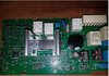
Did you give back info on the RED circled area . . . as I view it, it possibly just might be some ferrite beads on a wire.
I CAN make out a 200 and 100 ohm surface mount resistor and a centered transistor.
Notice that they make no effort to assign designations to any components on the board.
Since this unit is typically being mounted in an enclosed " sarcophagus " for shock and humidity / water protection, one can only SEE the board when it is exposed . . . such as you now have it.

SURELY that TNY unit is bad . .at 36 ohms . . . D to S and the open supply resistor that feeds the power supply for it.
If you want to confirm the proper value of that open metal film resistor, try this.
I am reading it as brown black brown and a gold or silver tolerance band. . . . with an insignificant very end band.
That would make it 100 ohms . . .totally realistic.

To test, take a single edge razor blade and VERY carefully scrape away a bit of the paint cover in the very center of the resistor.
Take ohmmeter in a suspected 100 ohm range scale and touch one meter lead to the wire lead at either end of the resistor and then see if a reading is obtained with the other leads probe as it is touched onto the very center, of the just scraped area.
If no reading, then move from one resistor end lead to the other , in reading to that central area.
With the next paint scraping . . or another . . . if required.
A reading should eventually show up from one of those ends to the center. Double that value and you have the value of the blown resistor.

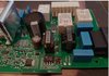
Here is how I am " reading " other areas:

Main AC power input at A connector and then as activated, power relay B or B' feed power down to A' as either a motor or water heating element supply.

AC line from A also gets line filtering with C series of X and or Y cap types. AC then passes thru dual AC inductive line filter for EMI / RFI at D.
AC line from D makes its way down to J ( now open resistor ) passes thru and then needs to find its way to a usual used Full Wave Rectifier Bridge * to get DC voltage for the main B plus storage capacitor H.
I can't see it * in the picture.
Also you need to test K and L to see if they are two power diodes or ferrite shielded feed thru lines . . .which would test out as shorts.

Back up at E is your shorted TNY which is relying on its B+ supply from cap H . . .I can read 100 ufd . . .is its voltage rating on up around 400 VDC ?
If E was working, it would drive low voltage power transformer F which then supplies its voltage to be rectified and feed into G storage capacitor. That meets the low voltage DC supplies for the circuit board .
Check the part numbers and give feedback on items M and N, as M looks like it could be a power dual Schottky rectifier, or and looks like N could either be a 3 terminal regulator or power FET.

Need more picture coverage of P, as some SERIOUS " bidness " is going on over there, possibly power and adjustable speed control of main motor.

BTW . . . . don't you realize that YOUR problem is deviating from the norm . . . . . with the USUAL failure mode, being one of the high current handling terminals on B , B' or the other like big relay nearby having developed into the condition as is being shown on inset A below..

PCB MARKUP :


View attachment 29198


73's de Edd

Ok, thank you, I'll try
I was advised to use 100 ohm 3 watt fusible resistor. I could not find the fusible resistor so I just used 100 ohm 3 watt resistor. I also used TNY266GN instead of TNY264GN. One can use higher value tiny switch without any issue.

Be careful when soldering TNY switch.
When I replaced the TNY264GN, it didn't work. It was either dead on arrival or I burned it during soldering job or I didn't solder it properly. Then I replaced it with TNY266GN and this time I soldered it carefully and it worked. The only reason I used TNY266GN is that I got it cheaper. If you are a pro then you know about soldering and if you are a diyer then watch some YouTube videos to solder smd chips.

Thanks to this thread and the post by 73's de Edd, I managed to fix my Bosch SMS69L22GB/55 dishwasher. I had almost discarded it and ordered a new one as it was 8 year old. After reading your post and another fellow's post on uk whitegoods forum, I decided to have a go. I found that 100 ohm resistor was burned. TNY264GN had no obvious damage but pins 3 and 5 were short. Replaced both the components and dishwasher is working as before. Thanks to you guys, saved me £500-600.

One more thing I would like to point out is that when dishwasher broke down it was running a 29 minute quick wash cycle For a month the dishwasher has been left unplugged and power board removed. Still when finally fixed it came back with quick wash cycle, showing 21 minutes remaining. I don't know how it retained this memory as I can't see any battery on the board.
 
Last edited by a moderator:
I have a similar fault with a Neff Dishwasher which shares what looks like an identical PCB. I'll upload the photo. I can see black marks on one of the blue capacitors although the cap itself isn't swolen or melted. The transistor/diode, resistors caps appear undamaged, but there is a suspicious hole /crack on the end of the TNY264GN package.
Measurements so far:
TNY264GN
Pin 2-5 24.2Ohms
Pin 3-5 24.2Ohms
Small "6CW18" transistor next to the TNY seems to have under 0.04V across all combinations of diode test combinations, but done in circuit.
Diode by TNY measured using diode test gives 0.53V in one direction, 0.5V in the other direction rising to 1.1V over a few seconds then stabilising.
100 Ohm resistor measures 100Ohms
200 Ohm resistor measures 199Ohms
100 Ohm 2W resistor measures 99Ohms

So my plan is to order a new TNY part, but not sure what could have caused it to fail, and what other parts I should replace at the same time. The transistor doesn't look damaged but those readings don't make much sense to me. Googling for the part 6CW18 only gives a full part number of TS1086CW18 https://www.alldatasheet.com/datasheet-pdf/pdf/123727/TSC/TS1086CW18.html but that is not a transistor, it's a voltage regulator in a different package. I note from one of the other photos above has an alternative part marked "CW19". A separate forum post https://www.elektroda.com/rtvforum/topic3373119.html suggests it may be a BC817-40, but that doesn't match up with the markings so a bit confused as to what this part can be replaced with.

Any suggestions greatly appreciated.
View attachment 50317 View attachment 50318 View attachment 50319
 
It's possible a dodgy capacitor shorted there (perhaps it leaked and dried out), as I agree with you it doesn't look like anything else is obviously bad. I would replace those caps first, as they are easy, and go from there with the TNY and support components
 
On further inspection there is also a vapourised track under the capacitor (which I removed to see better what happened to the PCB) near the 2w resistor, i have not yet figured out what that track is for - it is connected to the + side of the large electrolytic, so should have mid 300v on it, going to a surface mount rectifier which can't be one of the 4 rectifiers in the bridge (can't find them), because the track is tiny. I have removed the TNY part so I could probe surrounding parts without it in place, and so far they look ok, but a bit stuck now as I cannot locate the bridge rectifier anywhere which I'd like to check is intact before putting the low voltage power circuit back together. track vapour.jpg scorch2.jpg IMG_8005b.jpg IMG_8005a.jpg
 
Yes, not sure what that track is for without seeing more of a circuit diagram. That diode has a chunky reverse breakdown so it would have needed to be a big surge, though if the diode did break down then it would certainly fry that track - so perhaps it was used as a sort of emergency fuse somehow.... weird!
 
Top