Hi everyone,
I will need help. Can somebody help me. I made a circiut like on picture. It's working well when I connect the burden 3A. When I connect burden to 6 A the mosfet getting hot. I need your help.
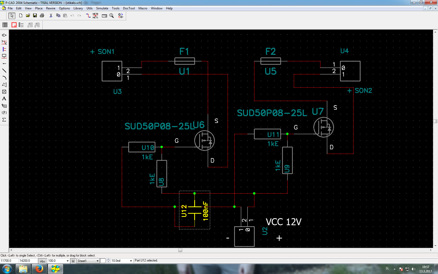
Image: http://file.slo-podnapisi.net/slikomat/datoteka/ntnjzxzjty2ynuzhwhjg.jpg
Thank you
I will need help. Can somebody help me. I made a circiut like on picture. It's working well when I connect the burden 3A. When I connect burden to 6 A the mosfet getting hot. I need your help.
Image: http://file.slo-podnapisi.net/slikomat/datoteka/ntnjzxzjty2ynuzhwhjg.jpg
Thank you
