Maker Pro
Maker Pro

Optocoupler delay off MOSFET solenoid

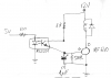
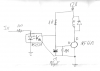
This is to trigger a 12v solenoid (acting as a laser shutter) with 5v (JP2) thru an optocoupler.
The problem is 5v line have bit fast interruptions on a laser show, so I'd like to add a bit of delay OFF (say 0,5sec) in order the shutter remains active (energised) when this little interruptions happens (you know, to avoid click-click shutter open-close noise) So I think I need to put a capacitor and maybe resistor+capacitor, but sorry, I don't know where on this circuit...
Could you help me please?
Many thanks
Oscar (Spain)
 

Attachments

  • solenoid-1.png
    solenoid-1.png
    3.7 KB · Views: 242
Welcome to EP!
If I've understood your intention correctly I think you should connect the emitter to the +ve end of the cap instead of to ground, and disconnect the collector from the +ve end of the cap. You might need to reduce either the cap value or the 1meg value.
 

hevans1944

Hop - AC8NS
Many thanks! :)
Something like this one?
Your circuit will turn on the relay when the opto-coupler is turned on and charge up the capacitor, which will then discharge through the 500 kΩ resistor when the opto-coupler is turned off. The MOSFET will remain on for a short time until the capacitor discharges sufficiently to make the MOSFET begin to turn off. At this point the MOSFET will enter a linear conduction mode and begin to reduce current to the relay coil. When the current has been reduced sufficiently, the relay will drop out. This may not be desirable operation because it increases the power dissipation in the MOSFET, which previously was essentially zero when the MOSFET is fully conducting, during the transition period.

But the circuit is simple enough to be worth a try. You can add more complicated Schmitt-trigger type switching later if the MOSFET doesn't turn off fast enough after the time delay.
 
"The problem is 5v line have bit fast interruptions on a laser show"

What do you mean by "fast-interruptions"?
What is creating the "5V signal"?

and another thing,
why do you need a relay to switch the laser?
 
There is an interface (dac) connected to a pc with a laser show app.
The dac supplies several 5v channels: basically 4 channels at 5v analog modulated channels (0 to 5v): one modulates red intensity laser, other green, other blue, and the last one, is the shutter.
The shutter is a solenoid which 'blocks' laser output when no 5v is present. this is a safety feature.
When running a laser show, the 5v channel which drives the shutter driver (mosfet etc) is ON when laser beams are present, so ON, shutter doesnt block laser, so solenoid is energised.
However, on a show, there are lots of 'fade' moments where laser beams are off, on this brief and quick moments, the signal to shutter goes also to off (iss 0-5v TTL), so on a show, the shutter is always..click-click open-close, open-close.

If a bit of delay-off is added on the mosfet, the shutter remains energised on that brief 0v interruptions (where laser beams are off), so we avoid such click-click shutter noise during a show. However, a manual e-stop is implemented on the mosfet to fast turn shutter off if necessary and block laser out.
Hope this explanation helps...sorry too much extended

btw, there is a way to calculate delay-off time on above circuit?
could be the 500k resistor replaced by a 500k trimmer in order to adjust delay off time?
Many thanks guys! :)
 
I would move the delay to be on the "5v-signal side".
If I understand correctly you need the delay only on the
shutter-on to shutter-off transition,the other way there should be no delay at all.
 
sorry not exactly, When 5v 'trigger' is off, the solenoid should remain active say...0,5sec more, so this is a delay off if I'm not wrong.
When 5v is active, solenoid should be energised asap, so I dont need 'delay on'
 
O.K
replace the "5V-signal" with this circuit:
Inverters are schmidt-triggers (one 74HC14).
One silicon-Diode.
Tdelay is set by R-C .

dealy- off.JPG
 

hevans1944

Hop - AC8NS
A negative edge-triggered delay on the opto-isolator input would work. You would logically OR the input to the opto-isolator with the output of a negative edge-triggered one-shot multivibrator and then use the OR gate output to drive the opto-isolator. There will be a short "glitch" lasting a few nanoseconds when the input goes low, before the one-shot output goes high, and then the opto-isolator remains on for 0.5 seconds. The "glitch" will not be long enough in duration to allow the relay to drop out. This is probably a bit of over-design compared to @dorke's circuit.

@dorke's circuit should work. The capacitor will charge up toward Vcc through the resistor R while the input is low (laser shutter closed) and the first Schmidt inverter output is high. When the input goes high, the capacitor quickly discharges through the diode to logic low level and produces a logic high output from the second Schmidt inverter to energize the opto-coupler and the relay, opening the laser shutter.

When the input goes low, the capacitor begins to charge through the resistor R until, after a delay, a logic high level is reached at the input of the second Schmidt inverter, upon which event the output of the second Schmidt inverter goes low, closing the shutter.

What happens if the input goes high again shortly after it went low? The capacitor may not have time to fully discharge and will continue to assert a high level to the second Schmidt inverter for a few milliseconds. This should not present a problem though because the diode D will now rapidly complete the discharge of C and that will be reflected as a high output from the second Schmidt inverter.

What happens if the input goes low shortly after it goes high? The capacitor will quickly discharge through D while the input is high, even if this is only a few milliseconds duration, so when the input goes low the capacitor is ready to delay the return of the output to a low state and so begins the half-second hold up delay when the input goes low.

Someone should construct @dorke's circuit on a solderless breadboard, post some oscilloscope waveform capture images, and clear pictures of the breadboard circuit. The OP can then copy the breadboard layout, perhaps transferring the circuit to veroboard or similar prototyping board.
 
Last edited:
many thanks, however I have 0 skills on electronics, sorry, need something more simple and how to wire it...
how about this one? Could we setup "switch delay off" time adjusting 500k trimmer?
many thanks
 

Attachments

  • solenoid-mosfet.png
    solenoid-mosfet.png
    56 KB · Views: 314
Oscar,
If we go to the beginning,in order to be able to help you with the best solution.
A few questions:

1. What is creating the "5V signal"? a photo?
2. What is the connection to the Laser shutter ? Is the solenoid an integral part of the system or something you added? a photo of the solenoid ? what is written on it?
 
The circuit in post #14 is worth a try, but put the 10k in series with the trimmer instead of in parallel. Without the 10k in series you could have quite high current through the trimmer if it were set to near-zero Ohms inadvertently. With the 10k in parallel you are shunting the trimmer and making it ineffective/difficult to adjust.
 

hevans1944

Hop - AC8NS
or maybe this one??
All of your circuit variations have a capacitor in parallel with the gate-to-source terminals of the MOSFET switch. The capacitor holds enough charge to keep the MOSFET conducting when the 4N35M opto-isolator turns off. One or more resistors in parallel with the capacitor (or in one instance, also in series with it) determine how fast the capacitor discharges when the 4N35M turns off.

As I said in post #5, go ahead and try this. The problem is the capacitor discharges along an exponential curve, quickly at first and then more slowly as the voltage across the capacitor approaches zero. Somewhere in between, the IRF540 will stop being a closed switch with a low resistance from source-to-drain and enter a linear conduction region where the resistance begins to increase. Eventually the capacitor will have discharged below the threshold gate-to-source voltage and the IRF540 will essentially be turned off, presenting a high resistance from source-to-drain.

During the length of time the IRF540 spends in the linear conduction region it is dissipating power, perhaps not a lot of power depending on the amount of current the solenoid coil resistance and the source-to-drain resistance allows, but it is some power versus no power when the MOSFET is fully conducting or fully non-conducting. How much power the IRF540 dissipates during this switching interval from fully-on to fully-off may be insignificant for your application because it occurs infrequently. And if that is true, your capacitor-resistor turn-off delay will work just fine. However, @dorke's Schmidt inverter solution is better engineering practice.

BTW, I would replace the word "shutter" with the word "douser" which is used to describe a shutter that operates to block intense light even if the light is still on. Widely used in theater film projectors, the douser protects the film from the intense illumination source, if for some reason the film doesn't advance through the film gate. Years ago I worked with a water-cooled douser that was placed at the common axial focal point of two ellipsoidal mirrors. One mirror had an intense electric arc at one of its foci and the other mirror had a test specimen at one of its foci. The douser in between, at the foci common to the two mirrors, determined when the image of the arc was focused onto the test specimen, simulating the effects that would occur near ground zero in a nuclear explosion. With the douser initially closed, the arc was ignited just before the experiment began and remained on during the experiment. The douser operated very rapidly, both to provide a good simulation and to prevent it from burning up while the arc was on. The arc was electrically extinguished immediately after the douser closed at the end of the experiment. Who would of thunk you could simulate the effects of a nuclear bomb using table-top apparatus? Well, pretty large table, but table-top nevertheless. Pretty damn big arc too.
 
Top