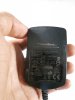
This is clearly a shielding and power supply problem. The switch-mode power supply is probably responsible for the interference. Try wrapping the sensor ribbon cable in aluminum foil and, using a short jumper wire with alligator clips on each end, connect the end of the foil farthest from the sensor module to circuit common. Do the same thing for the DC power cord from the "wall wart" power supply. If this "fixes" the problem you can replace these two cables with shielded cable.
Also, viewing the second video,I didn't see a single by-pass or power supply filtering capacitor on the main circuit board! What were you thinking? Do you have an oscilloscope you can use to look for this "noise" that is ruining an otherwise fine project? Nice circuit board construction, BTW.
Thanks for the quick reply and the compliment
")
I had tried using shielded wire for the encoder, however it did not solve the issue. As you said, maybe I need a shielded power supply cable..ill try that..
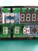
I have made provision on the PCB to attach filter capacitors and I did try various values 1uF, 10uF etc. but it did not affect the interference in the slightest way.. I am not sure how to find out which capacitor value to use. Unfortunately, I do not have an oscilloscope!
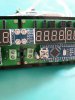
Image: Notice the two holes on the PCB between Arduino and terminal block? Thats where a capacitor can be inserted as shown in the next image...