Maker Pro
Maker Pro

Optical Encoder Issue

Hello friends this is my first post on this forum!

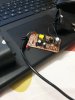
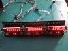
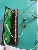
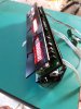
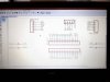
I have built a coordinate measuring and display unit with the help of optical encoder, raster strip, Arduino Nano, and MAX7219 LED display module.

The number displayed on the LED module should increment or decrement depending on the direction of motion of the encoder strip between the optical encoder. When the strip is not moving, the value displayed on the LED module should remain the same.

The problem is that the value displayed on the LED module keeps on incrementing and decrementing randomly even when the strip is stationery.

The only way I found out to prevent this is to touch any part of the circuit. If I touch the pcb with just my fingertip, the fluctuations reduce but don't stop. However, if I hold the pcb tightly or if the area of contact is sufficiently large then the value remains still and everything works well.

I dont think this is a grounding issue because it works perfectly even if I touch the +ve pin or ANY other pin for that matter. It works even when I hold the insulated power cable in my hand AND press tightly.

Touching a large metallic object to the pins also solves the problem.

Please take a look at this video that I have uploaded to youtube.

 
I too would say a grounding issue, I see you are using a Wall Wart, try it with a battery.
Also if it persists, try an earth ground to supply common.
Also try local de-coupling, place a small electrolytic across the supply terminals.
M.
 
Last edited:
Thankyou for your reply Bob. Ill post the schematic for you. There is a common ground between the two.
 

Attachments

  • encoder pcb.JPG
    encoder pcb.JPG
    32.1 KB · Views: 111
I too would say a grounding issue, I see you are using a Wall Wart, try it with a battery.
Also if it persists, try an earth ground to supply common.
Also try local de-coupling, place a small electrolytic across the supply terminals.
M.

Thankyou for posting Mr.Minder! I would like to know whether it can be a grounding issue even when the problem solves when I touch the +ve pin, not just the grround pin.

Since it is a two pin power supply I couldnt use the ground wire but like you suggested, I tried touching a ground wire from the power socket to the USB jack and the value stabilizes. But the same thing happens when I touch a large metallic object to the pins...it works even then

I tried adding various capacitors across the power supply but they dint seem to affect it at all.
I tried 1uF and 10uF among others.

Like you said, I tried running it off batteries and it WORKS flawlessly! :)
But I would really like to supply it via an adapter or a power supply unit for future use..

I have attached a link to another video I took
 
With earth grounding it does not matter if you earth ground the +ve or the common, they are identical as far as noise is concerned. Especially when de-coupled by a large Cap.
It does seem like radiated noise from the external AC.
I assume that P.S. is a SMPS supply, I would bet it may not happen with a small linear P.S. that has better galvanic isolation.
M.

I got your point regarding the grounding..

P.S. is just a cheap 5V cell phone charger.. The white device it is attached to is the extension cable...
I have attached a pic of the insides of the charger
 

Attachments

  • 20160613_231304(0).jpg
    20160613_231304(0).jpg
    274.6 KB · Views: 97
Would this issue solve if I use a good quality switching power supply?
Can the problem be solved by making changes to the cell phone charger circuit?
I notice that it has a transformer with a floating neutral.. Can that be the cause of the noise?
 
Not quite sure what you mean by 'floating neutral' but the live and N are normally isolated from the output, but in some cases input filter components can be also be connected from AC to output.
Only a test would find out if a better SMPS supply would work.
I don't there would be any future in trying to modify the existing supply.
M.

By floating neutral I meant that the output neutral of the transformer isnt connected to the input neutral..( I actually tried doing this and got a mild shock on touching the encoder wire! )

Alright, Ill invest in a SMPS dual power supply then. 5V for the arduino and 24V to run the stepper motors. (To run the gantry)
But I still haven't understood what is causing the problem. Can you confirm that it is a power supply noise problem?
Is this a common problem and can it be solved by using decoupling caps? How can their values be determined?
 
Without having the unit to test I can neither confirm or deny it is P.S. or other noise.
It is mainly a question of taking one of the actions shown above in order to eliminate it.
There is a part of the circuit that appears susceptible to radiated (AC) noise.
If you post the circuit, it may be evident where sensitive part of the circuit may be.
M.
 
Tell us about the encoder. Is it mechanical? If it is, and it simply closes a switch periodically when you rotate it, have you used a pull-up or pull-down resistor on the input to the Arduino? If not, the input is floating whenever the encoder switch is open and could cause this behavior.

Bob
 
The 'Encoder' appears to be a home made slot opto and a quadrature strip, If so for bi-direction you need two detectors.
But these usually have fairly low in/out impedance, did you provide a suitable value for pull up on the output?
I am guessing that your problem lies in this area, still no schematic?
M.
 

hevans1944

Hop - AC8NS
Tell us about the encoder. Is it mechanical? If it is, and it simply closes a switch periodically when you rotate it, have you used a pull-up or pull-down resistor on the input to the Arduino? If not, the input is floating whenever the encoder switch is open and could cause this behavior.

Bob
It is an Agilent HP 9730 with two quadrature-spaced detectors and a single LED illumination with integrated lens. This is to be used with a "bar and window" strip of appropriate cycles per unit length to create quadrature outputs on two channels. It is also suitable for use with a rotary encoder of appropriate "bar and window" spacing. The outputs feature integrated pull=up resistors, so it can be connected directly to Arduino digital inputs for direction decoding and position incrementing or decrementing.

@MihirS appears to have this decoded and displayed properly, and is only having problems with exterior coupling of interfering nearby mains wiring, probably from the "cheap" cell phone recharger. It would be nice if he uploaded the schematic instead of just the board layout, along with the code he wrote for the Arduino. :D
 
Thankyou for replies.. for some reason, I did not get an email notification about newer replies so I did not check this forum.

hevans 1944 is correct, I have used an Agilent H9730 quadrature optical encoder. The encoder and the strip which has 180 lines per inch resolution has been purchased from China.

The schematic is very straight forward.
The inputs of the encoder A and B have been attached to the two interrupts of the Arduino and are triggered on 'CHANGE' in state. I have programmed it in 4x decoding mode. The LED module pins (DIN, CS and CLK) are attached to pins 10 11 and 12 of Arduino.
Thats all there is to it. The GND is common for Arduino, Encoder and MAX7219 LED Module.

As Minder had suggested, when I tried running it off four 1.5V AA batteries in series, it worked perfectly. However, I have 3 such similar units, one for X, Y, and Z axis (see attached image). When I powered all the units with the batteries (all connected in parallel), I again got the same problem, but this time I suspect it was due to insufficient current supply by the batteries. It works fine if I take out two of the LED modules. Should I try with higher capacity batteries? But still it wont be a permanent solution....

Schematic is finally attached! :)

Update: The whole unit (X, Y, and Z) consumes 520mA at 5V.
 

Attachments

  • 1466742530400-1841423147.jpg
    1466742530400-1841423147.jpg
    236.4 KB · Views: 59
  • 1466742741190-2065140398.jpg
    1466742741190-2065140398.jpg
    257.1 KB · Views: 104
  • 1466742839780-1057364252.jpg
    1466742839780-1057364252.jpg
    228.1 KB · Views: 108
  • 14667433771331250957138.jpg
    14667433771331250957138.jpg
    175.5 KB · Views: 103
Last edited:
It is an Agilent HP 9730 with two quadrature-spaced detectors and a single LED illumination with integrated lens. This is to be used with a "bar and window" strip of appropriate cycles per unit length to create quadrature outputs on two channels. It is also suitable for use with a rotary encoder of appropriate "bar and window" spacing. The outputs feature integrated pull=up resistors, so it can be connected directly to Arduino digital inputs for direction decoding and position incrementing or decrementing.

@MihirS appears to have this decoded and displayed properly, and is only having problems with exterior coupling of interfering nearby mains wiring, probably from the "cheap" cell phone recharger. It would be nice if he uploaded the schematic instead of just the board layout, along with the code he wrote for the Arduino. :D

Thanks for explaining :)
 

hevans1944

Hop - AC8NS
This is clearly a shielding and power supply problem. The switch-mode power supply is probably responsible for the interference. Try wrapping the sensor ribbon cable in aluminum foil and, using a short jumper wire with alligator clips on each end, connect the end of the foil farthest from the sensor module to circuit common. Do the same thing for the DC power cord from the "wall wart" power supply. If this "fixes" the problem you can replace these two cables with shielded cable.

Also, viewing the second video,I didn't see a single by-pass or power supply filtering capacitor on the main circuit board! What were you thinking? Do you have an oscilloscope you can use to look for this "noise" that is ruining an otherwise fine project? Nice circuit board construction, BTW.
 
Top