Hi, I'd like some advice on a circuit I'm designing for audio output.
I'm making a simple game system from PIC chip. For the audio side, I'm going to be using four of the GPIOs as a basic four-channel mono sound generator. The PIC will have a whole bunch of accurate hardware timers in it so I figure that if I set up four channels with a timer and GPIO pin each, I can write a service routine for each timer that flips the given GPIO bit when the timer expires. This means I will get four channel square wave output for next to no computation cost.
Because these are GPIO, they're going to be 0V to whatever high voltage is (CMOS high so it's 2.6V ish according to the datasheet). These are supposed to be logic data CMOS pins so obviously I want to source or sink as little current as possible and so I definitely need to buffer them before sending it to a speaker.
I need to sum the output voltages and output the result to a speaker or mounted audio jack socket to get my sound out. I have a box of 4 ohm, 10 ohm loose loudspeakers that can go on the end, but I don't know what amplifier circuit to use. The objective is to do this as simply, safely, cheaply and awesomely as possible. Audio quality isn't going to be great no matter what so it's not a big priority; it'll sound like a Master System at best (and I've programmed MS sound before, it's not pleasant). My idea is to build a little one or two transistor buffer stage to the side (or whatever's reasonable) that means I can clip on the speaker and not worry about damaging the MCU. I'm running this from 3.3V on 3 x batteries.
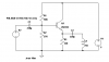
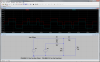
This image is the circuit I have in mind.

On the left are the GPIO pins A through D, connected into a resistor summing junction. It's a big voltage divider. I can pick the values of R and Rg to scale the maximum result voltage at 'all pins HIGH at once' to whatever range I want between 0V and 2.6V max. (Output impedance is given by R/4 // Rg.) This part is pretty much settled. The selection of the output impedance and voltage scale are the parameters that need to be chosen, they'll need to be selected to fit along with the amplifier stage on the right.
On the right is an emitter follower (the most basic transistor buffer I think). For a circuit like this (or any other transistor amp stage) I need to calculate the R and C values to set the base bias voltage, voltage gain factor and power draw to whatever is 'appropriate' and it's done: high input impedance for the GPIOs but low output impedance and high power for the speaker... but I don't know what voltage gain I should be aiming for for these loudspeaker components, or what voltage scale to aim for. I've been reading the Art of Electronics and all that over and over, but I'm afraid it's all going over my head.
Alternatively, an op-amp could be used on the right, set to straight-forward buffering to reproduce the signal exactly (with a decoupling capacitor in series to the speakers to prevent them getting DC?). This might be the way to go, but I would still need to know whether the output is suitable for driving a loudspeaker. I might need to combine an op-amp in buffer mode with a transistor to provide the appropriate drive. (Similar to this, op-amp output into the transistor base, inverting input op-amp feedback from transistor result. http://i.stack.imgur.com/KetKx.png)
Please let me know if I'm onto the right track, and recommend any circuits and components you think will help.
Many thanks.
I'm making a simple game system from PIC chip. For the audio side, I'm going to be using four of the GPIOs as a basic four-channel mono sound generator. The PIC will have a whole bunch of accurate hardware timers in it so I figure that if I set up four channels with a timer and GPIO pin each, I can write a service routine for each timer that flips the given GPIO bit when the timer expires. This means I will get four channel square wave output for next to no computation cost.
Because these are GPIO, they're going to be 0V to whatever high voltage is (CMOS high so it's 2.6V ish according to the datasheet). These are supposed to be logic data CMOS pins so obviously I want to source or sink as little current as possible and so I definitely need to buffer them before sending it to a speaker.
I need to sum the output voltages and output the result to a speaker or mounted audio jack socket to get my sound out. I have a box of 4 ohm, 10 ohm loose loudspeakers that can go on the end, but I don't know what amplifier circuit to use. The objective is to do this as simply, safely, cheaply and awesomely as possible. Audio quality isn't going to be great no matter what so it's not a big priority; it'll sound like a Master System at best (and I've programmed MS sound before, it's not pleasant). My idea is to build a little one or two transistor buffer stage to the side (or whatever's reasonable) that means I can clip on the speaker and not worry about damaging the MCU. I'm running this from 3.3V on 3 x batteries.
This image is the circuit I have in mind.
On the left are the GPIO pins A through D, connected into a resistor summing junction. It's a big voltage divider. I can pick the values of R and Rg to scale the maximum result voltage at 'all pins HIGH at once' to whatever range I want between 0V and 2.6V max. (Output impedance is given by R/4 // Rg.) This part is pretty much settled. The selection of the output impedance and voltage scale are the parameters that need to be chosen, they'll need to be selected to fit along with the amplifier stage on the right.
On the right is an emitter follower (the most basic transistor buffer I think). For a circuit like this (or any other transistor amp stage) I need to calculate the R and C values to set the base bias voltage, voltage gain factor and power draw to whatever is 'appropriate' and it's done: high input impedance for the GPIOs but low output impedance and high power for the speaker... but I don't know what voltage gain I should be aiming for for these loudspeaker components, or what voltage scale to aim for. I've been reading the Art of Electronics and all that over and over, but I'm afraid it's all going over my head.
Alternatively, an op-amp could be used on the right, set to straight-forward buffering to reproduce the signal exactly (with a decoupling capacitor in series to the speakers to prevent them getting DC?). This might be the way to go, but I would still need to know whether the output is suitable for driving a loudspeaker. I might need to combine an op-amp in buffer mode with a transistor to provide the appropriate drive. (Similar to this, op-amp output into the transistor base, inverting input op-amp feedback from transistor result. http://i.stack.imgur.com/KetKx.png)
Please let me know if I'm onto the right track, and recommend any circuits and components you think will help.
Many thanks.
Last edited:
")