Hi!
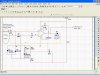
This circuit is part of an electronic card used as an interface in a flow meter. An inductive sensor which operate without being powered counts the rotations of the turbine; then transmits the signal to the pins 24,pin25 and shield of the circuit (Refer to the picture). The output of the op-amp drives a "Nand" Cmos gate. Note that there are two similar circuits as there are two sensors ne on the x-axis and the other to the y-axis. Each sensor is connected to a separate circuit similar to the one shown.
I whould like to know if the circuit is a linear or a non-liear op-amp application and the operation of this circuit?
Thank you in advance for your time and consideration.
This circuit is part of an electronic card used as an interface in a flow meter. An inductive sensor which operate without being powered counts the rotations of the turbine; then transmits the signal to the pins 24,pin25 and shield of the circuit (Refer to the picture). The output of the op-amp drives a "Nand" Cmos gate. Note that there are two similar circuits as there are two sensors
ne on the x-axis and the other to the y-axis. Each sensor is connected to a separate circuit similar to the one shown.I whould like to know if the circuit is a linear or a non-liear op-amp application and the operation of this circuit?
Thank you in advance for your time and consideration.