A "Low Current In-circuit Monitor"
Ross built a couple of these. At this point I'm not sure if there were design improvements or if he just needed more than one.

As usual, the documentation is printed on the outside. The instructions don't specify the power supply voltage, but as Ross was keen on using 12V lead-acid batteries, I think that it's a safe bet.


It's odd that the accuracy falls off at high currents. Why is that?
Power supply and meter connections are on the side (sorry about the focus).

Hmmmm... 0.24Ω resistance is a bit odd. If this contains a current sense resistor, 0.1Ω plus a bit for lead resistance etc would make more sense.
I also noticed there's a bit of a rattle inside...

And look at that extention to the trimpot's shaft. Looks like a quick job on the lathe.
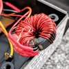
But Surprise! Is that a transformer? An inductor? Is this for AC measurement? It didn't seem that way???
Let's take a closer look:

Aha! Ross has very careful taken a slice out of a ferrite core and inserted a hall-effect sensor.
It stands to reason then, that the current measurements are taken with no common electrical connection to the circuit under test. I imagine that the series inductance is probably fairly high though.
This also explains the drop in accuracy at higher currents. I imagine that the core is saturating and the Hall effect sensor is no longer seeing a linear rise in flux with current. The other explanation might be that there are non-linearities in the hall sensor, but they're generally pretty linear.
The circuit uses
- 1 x LM324
- 1 x 78L05
- 6 x resistors 3 x 10kΩ, 2 x 120kΩ, 1 x 62kΩ
- 1 x 10 turn 5kΩ trimpot
- 1 x hall effect device (permanently epoxied in place)
I'll disassemble this further, but I suspect that the 5V regulator provides a stable voltage to the Hall sensor, at least some of those resistors are there (in conjunction with 1/4 of the LM324) to provide a 0V rail.
There seems to be no internal calibration, so I assume that the calibration was done by varying the number of turns on the coil (unless there's some very fortuitously selected resistors in there).
An image of this board from the top will not be very revealing, so here are some from an angle


And one from the bottom that is fairly perpendicular.

Uninsulated links on the bottom side! (and there's one on the top side too)
The shaft added to the trimpot is worth a closer look.

I can't be sure if that is teflon tape added to give a tighter fit or to make it turn smoothly against the body of the trimpot. I've tried to gently remove the shaft, but I don't want to damage it. It may be epoxied in place.
I'll have to measure the resistance of this trimpot because the added shaft hides the markings.
And oh dear, that's not a great solder joint there :-(
I don't have time to do the reverse engineering right now, maybe later (later has arrived).

The points labelled A, B, and C are the connection to the hall effect sensor. After labeling everything else up, it's pretty clear they are +5V, gnd, and output.
And here it is:

As suspected, there is no adjustment for gain, so the calibration must have been by adding and subtracting windings from the core until it was close enough!
It's also interesting that R6 and R7 are in parallel, and R5 has a different value. Why wasn't a single resistor used instead of R6/R7 having the same value as R5? There is room on the board for a resistor in parallel with R5. It's a mystery.
It's also worth pointing out that there's obviously something going on with the feedback path for U1. It's all been linked together, but there's a number of holes here. Perhaps Ross was considering some amount of adjustable gain here?
As I was going through Ross' components, I noted that he had taken a number of 1% resistors and matched them. It's quite likely that R1 and R2 here are matched to give an accurate gain without needing adjustment.
Another interesting thing is that this circuit is upside-down, using the output of the hall effect sensor as the reference voltage. As drawn, if an increasing current causes an increase in the output voltage of the sensor, the output voltage would fall. The easy fix is to reverse the sense of the winding (effectively reversing the hall effect sensor). I wonder, however, if this contributes to the reduction in accuracy as current rises?
Time to power it up, and... nothing!
It turns out that the last thing I would normally check was the problem (and in a blow to Murphy, I checked it first). The on/off switch was open circuit. Since I really don't need to turn it off the easiest solution was to just solder both wires to the one terminal.
And it works!
Setting zero is remarkably tricky. Given that my meter reads 0.01mV (10μV) I guess that's not surprising. However the larger problem is drift. As it warms up it drifts a couple of mV and needs quite a bit of adjustment to keep it near zero. After about 10 minutes that settles down too.
How accurate is it? See below. From 10mA to 800mA the accuracy is within 2%. The error at 30mA is possibly due to a failure to check the zero. And the loss of accuracy (possibly due to saturation of the core) starts at about 600mA.

The next thing is to measure the inductance seen by the circuit. (time passes...)
I can't help myself. The inductance of the input is 671μH with a Q of 15 at 1kHz. That's a lot of inductance, so a circuit like this is really only suited to slowly changing DC values.
edit 1: updated values and a better copper side photo
edit 2: annotated copper layer
edit 3: added the schematic.
edit 4: test results
edit 5: I can't help myself (inductance)


