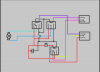
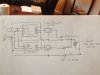
Alright, new project. I want to make a 2 bottle corking machine for my 100 or so cases of wine every year. I have a preliminary design worked up, and wanted to get some feedback on a couple of things. The essence of the design is this. Put wine bottle on machine, push button activate a linear actuator that extends to insert the crock and retracts. this means I will need to control the polarity so I can run the motor in reverse to retract the actuator. I't s simple design really, the actuators will throw 300 pounds of pressure down (which after checking other commercial ones seems more than enough) and force the cork through a tapered cylinder to compress it before it goes into the bottle. My least area of knowledge is in the electronics. I was thinking of using an on off delay timer x 2 to essentially provide power for 4 seconds, then turn off, and the other timer runs power for an additional 4 second at reverse polarity to retract it. This will be initiated by a click button. I know right off the bat my circuit needs two changes. Because my power supply is 24V 3A DC, the voltage regulator need to be BEFORE the timers, not after. AND at the end of the circuit the diode setup I thought would work won't, because I will end up putting power from both timers after the first activation. I have attached one of the timers I have, nice and inexpensive, but maybe Im overcomplicating it.
-
Categories
-
Platforms
-
Content
")