Maker Pro
Maker Pro

Older electronic Sliding gate opener, looking for wiring diagram or advice

New to the forum. Not sure where to even start looking, since I have no make model or numbers. But maybe someone here knows of an online source for wiring diagrams, or can help with the problem. I will try to describe it as best I can.

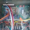
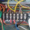
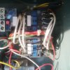
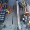
The gate opener is at least 20 years old, 3 phase motor, 24V contact and switches, has a forward and reverse relay, timer, inputs from limit switches. It has connections for remotes, but that is not in use. There are a couple of wires off of the 24Vtransformer that are not connected, but I assume must be power for the circuit board. But without a wiring diagram, or some hint about where the inputs would likely go, I'm lost. The motor works if I manually operate the relays, external switch is wired in correctly, so all that is left is to get power to the 24V circuit. By tracing the circuits on the board, is there any way to narrow down where the inputs may be likely to go? I could take pictures if it would help any
 
Good clear pictures of both sides of the circuit board would be a good start. Don't like your chances of finding a circuit diag of it.
 
Yeah. If you know the manufacturer/model number, someone might know your system. Pictures of the board will help.
I used to work on Stanley gate openers. They refused to supply schematics and their part numbers were proprietary. My boss had to call their service personnel, but I discovered when the repair person was done with each
repair, he had been installing replacement parts with regular JEDEC industry standard part numbers, not the proprietary Standly parts, and I got pretty good at diagnosing the future faults, now knowing the actual parts involved.
With a picture of the board, somebody should easily be able to tell you where input power should go. Hopefully, there won't be any additional faults you'll need to track down.
 
Here are some pictured of the front side, not much help, I realise. I can still removed it and get some from the back if it would be of any help.
The top 4 wires go directly to a switch in a building

The row of wires below that go to the junction panel below it, from there to the remote( not in use), the limit switches and the relays. And presumably power was supposed to come into the same panel. there are 2 24 V yellow and blue wires with the proper ends to go into the bar.
I've located the last electrician to have worked on this opener, who connected it to power and the external switch. He says he looked at the circuit board and concluded that it was garbage, and went no further. In my experience, that comment usually means he had no clue how it worked, or how to connect it, so blame the board. I know it did function before being set up in its current location.

Is there any reason why we can't bypass the circuit board? Install 2 latching relays activted by the Momentary On and Off push button switches( MO already installed in a building, hard wired in) Use the existing mechanically operated limit switches to unlatch the relays? Possibly install a timer for protection in case of obstruction or limit switch failure.

It already has 24V relays which are connected and working when manually operated. Overload protection for the motor and a built in resettable circuit breaker built into the 24V side of the transformer.

Any reason we can't do this? What other purpose would the circuit board have served, aside from connecting to the remotes?
 

Attachments

  • IMG_20141124_101523.jpg
    IMG_20141124_101523.jpg
    184.2 KB · Views: 1,499
  • IMG_20141124_101536.jpg
    IMG_20141124_101536.jpg
    210.9 KB · Views: 825
  • IMG_20141124_101539.jpg
    IMG_20141124_101539.jpg
    191.4 KB · Views: 1,028
  • IMG_20141124_101550.jpg
    IMG_20141124_101550.jpg
    156.8 KB · Views: 452
I don't see a picture of the transformer you talked about, with disconnected wires. The 3rd picture is of your open/close relay actuators, the 4th picture is of the limit switches for forward/reverse on gate movement.
Sure, there are plenty of companies that will sell you what you need.
How much are you paying that electrician?
He does have a point though. Without a schematic, things get harder to figure-out.
Have you got a manufacturer name or model number on the board, or something to Google search?
 
I've located the last electrician to have worked on this opener, who connected it to power and the external switch. He says he looked at the circuit board and concluded that it was garbage, and went no further. In my experience, that comment usually means he had no clue how it worked, or how to connect it, so blame the board. I know it did function before being set up in its current location.

In defence of the lecky, in my experience (as a lecky) it usually means there is no information available on how it works or what goes where or how to make adjustments, no circuit drawings available, the fact that "it used to work once" is no help what-so-ever, and basic tests for power is about all one can do given customers rarely (if ever) would want to pay for the time wasted trying to find a fault one has no hope in finding given the aformentioned.
 
Not faulting the electrician, given the complete lack of information available to him. I just wish people would admit that it is the lack of info that is the problem, not just announce that something is crap, when they really have no way of even testing or knowing that.
 
In many instances, due to the lack of service information , it is considered equipment to be just that as you describe (garbage) largely due to the fact it could cost an arm and a leg to reverse engineer.
These days it is considered normal to junk equipment after most failures, sad but true.
 
Top