Maker Pro
Maker Pro

Novel voltage doubler circuit need help plz

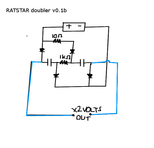
I've been working on my own design of voltage doublers/multipliers. The circuit here is a times 2, but you can add more caps to it easy enough for more voltage.
ratstardoubler.png


The idea for how it works is the capacitors are charged in sequence by the DC power supply, the first capacitor is shorted to, then once its filled the current diverts to the second capacitor. They must be charged in sequence, or they wont be filled to the top for times 2. If you charge them both at once they only half fill.

The diodes are there to stop the capacitors from discharging, the resistor values are to make sure voltage division doesnt cause too much loss on the collecting voltage.

Then they discharge in series, giving you a similar effect to batteries in series, they add their voltages together.

The circuit is tested and working, except for a strange problem I need help with.

I only get twice the voltage, if I turn the power supply off then test it. I know that I have to wait for both capacitors to be full before I test, this isnt the problem, it seems with the battery connected it only reads the volts of the power supply not the capacitors!

Note: I actually dont remove any leads, just switch the power supply off and bam I get double the volts, but when its on, its only registering the normal voltage, im not sure what it is!

The discharge path is open, and im just measuring both sides with the multimetre, with the megohm impedance or whatever the only thing connecting it.

Its completely tripping me out, not sure what to do.


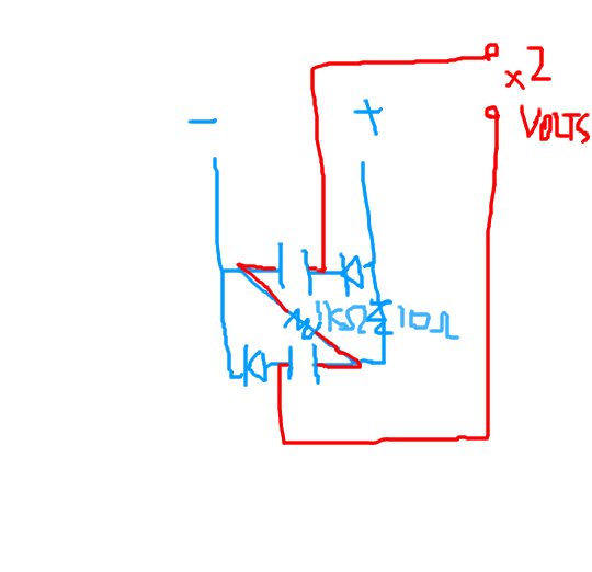
Heres another version of the circuit, and its just doing the exact same thing.
The blue is the charge. (and unless I remove this charge, I dont get twice the volts on the serial discharge.)
The red is the serial discharge.
circuit22.png
 
Last edited:
I made a 3 cap one, the voltage reading isnt above 30 volts! but im getting small numb electric shocks from it (im using electrolytics so i can get voltage readings.), maybe im not reading the voltage right.

When I read the caps one at a time, I do get the full voltage each time, but I cant seem to measure them together.

Is having resistors in the discharge line confusing the multimetre?
 
Last edited:
This voltage multiplier is different, works with dc! =)

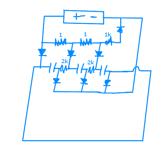
heres the 3 cap one's, schematic. I cant get a collected voltage reading, I wonder if its the 2k resistors confusing the meter??
When I read the caps separately they are all near the full 30 volts, and I was feeling a bit of the electricity in my fingers.

3capvoltmul.png

Think of the diodes as stoppers on the capacitors so they cant discharge,
and the resistors are controlling the path of the electricity, and also making sure the voltage division ratios are acceptable.

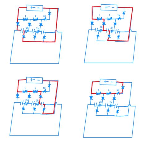
Heres the 4 phases of the system, It charges the capacitors one at a time, and thats how it achieves the high voltage.
AB
CD

151943873_1420310861650300_5898349532861142489_n.jpg
 
Last edited:

Harald Kapp

Moderator
Moderator
You cannot be helped: these circuits will not work with DC.
In order to have current through the capacitors, you will require an AC source. Otherwise the capacitors will charge once and then stay at this level without any further change in voltage across.
 
the capacitors will charge once and then stay at this level without any further change in voltage across.

You discharge it through a spark gap, then it just charges again, over and over.
Its the same as a spark gap oscillator. (Only needs DC,)

It is still rectified oscillated AC out. its like PWM sorta.
 
Last edited:
It's more of the style of a Marx generator with resistors for the spark gaps.

ha! Thanks for telling me, I thought this would have been done before.

Can you measure the collected voltage of a Marx generator? I only can seem to read the capacitances individually, not the collected voltage and I dont know why...

With big farads, these things are deadly, got to be careful and only use little caps, they actually work with lowish volt electrolytics, cause of the dc nature, scary amounts of easy power...
 
Last edited:
Im not making this thing to show off sparks, I need it to test electrostatic actuators, because i'm into graphite technology (which is just a fancier form of lead IMO), I'm only using really small spark gaps, the smallest I can manage, and using least volts and farads possible.

Then theres less chance of... accidents... and the circuit is more efficient.
 
That lesson is the most cryptic thing ive ever watched... I like to explain (normal ac ones) voltage doublers as pumps with the capacitors powered with the power supply. (instead of the capacitor doing the work, the wind is doing the work by itself :) ) just suck in, and blow out, suck in blow out, then I can actually understand whats going on and follow the circuit.
 
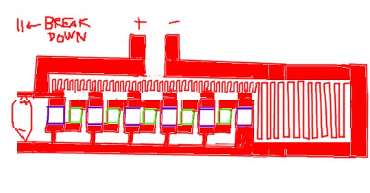
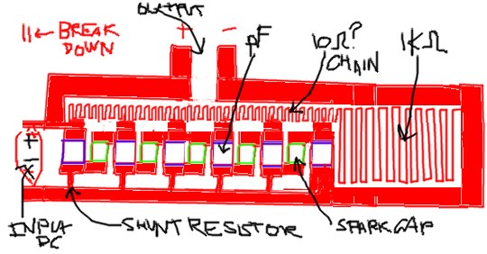
I hope this works, heres a marx generator put into printable IC form, im going to fab it with my 3d printer, and it cant even be that miniaturized because you have to spread it out to the breakdown distance, but if i make in a vacumous environment, its actually 10 times lower than air, so its good for when you have to put down a repeat compound, and the dielectric strength needs help, pump more air out of the system for higher volts? (later stages in the multiplier.)

The blue squares are the capacitors, and the green squares are the spark gaps,
the rest is conductor. I want to do a 2 embossment sandwhich, but it only counts as 1 sided board with jumpers... but like I said before if you remember, thats all I need to make anything. :p
151931389_1420670104947709_1811130313630724761_n.jpg

151623410_1420674178280635_3876716228879762617_n.jpg
 
Last edited:
BTW, I got it working, a 30 cap one, I cleared the spark gap by more than twice, and the hz is jumping around like mad, because its made out of copper tape, it goes from 20 hz to 1kilohert. When I closed the spark gap, it went to 0 hz, every time, so I think ive got it.

I read the oscillator from one side of the spark gap to the ground (negative), in "HZ" mode. I think thats right.

*Bows*

Thankyou my friends, I couldn't have done it without you, especially Harold. :)
 
Heres a video of it. (its not being run, just showing.)

In the middle of the circle is the spark gap I made out of copper tape and sit it under a set of drawers overnight to get it as flat as I could, I think its about a 400 volt one?

 
Last edited:
Marvel.

Its actually the first oscillator ive made that works. So its a big step for me.
I made one ages ago (Like 3 years ago) But I couldnt figure out how it worked, so I couldnt reproduce it.... took me long time...

So onto making my computer!!!
 
Last edited:
Your sketch of a pcb shows the output shorted to the DC input. Then the shunt resistor is discharging the DC input.

A resistor charging a capacitor then a spark gap discharging the capacitor is much too crude and an extremely old idea to be an oscillator today.
 
Top