Maker Pro
Maker Pro

Not really a repair, but some help going in the right direction appreciated

hello all, sorry my first post is asking for help, but i have a question about a fabric feeder i have. it has a motor inside that says it is a 110v motor, but apparently the unit itself has been wired for 220v, and it has the option of being wired for 110v, but reaching out to the company hasnt helped (it is an Amspak Movatex feeder)

i was wondering if anyone here could help me understand the main board, and how it is able to be wired for 220v and 110v. there isnt much on the board itself (pic below) but i am not sure where to start
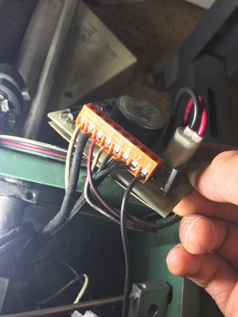
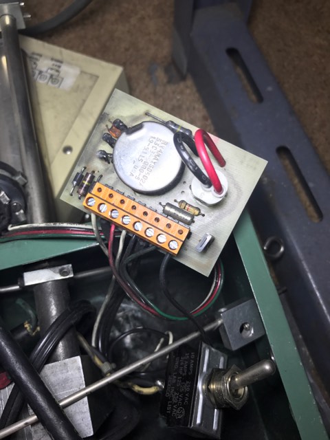
pic one:
#2 and #6 are power wires
#1 goes to the power switch
#8 goes to the fuse
#3,4,5 &7 go to a rotational lever type thing ( i dont know what it is called exactly)
7w3VZ1M.jpg


32i1V4g.jpg


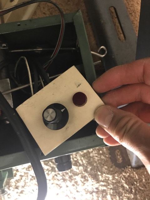
front side of panel:
fTQIRGF.jpg


any ideas where i can start looking to figure out how this works and switch it to 110v would be greatly appreciated
 
Sir fiveseven15 . . . . .

What I am seeing there is a panel with a 5K speed control pot and its associated solid state Triac controller that is at the end of the term board.
Assurredly, using a NEON based indicator lamp.
Can you fill us in on what is being the function of the toggle switch, and if there are 4? or possibly 6? wire connections being made into it.
Could the mystery lever be a directional reversal function ?

If this is for 220, seems like it should work slightly on 120 VAC input, for just enough time for evaluation of seeing if the moto runs and possibly adjusts.
We will also need to see the PCB foil pattern. in which you need to pull the knob and control nut just below it to take off the PCB from it.
Also, if physically accessible, a possible pic of the . . . . . rotational lever type thing . . . . .. at the end of that 4 wire cable.

73's de Edd
 
this switch? i believe this is an automatic shutoff, its supposed to rest on the fabric bein fed, and when the roll run out, the arm isnt held up by anything and falls
Gp9Wpao.jpg

Back
lWvMTDq.jpg


with arm mounted (but not clocked correctly)
Jd36oho.jpg


foil pattern:
g0MfBTv.jpg

backside
RPPywmn.jpg


i plugged it in, and the lights come on, but the switches and levers dont do anything. fuse isnt blown, but i dont have any idea of the motor condition. since the motor itself is labeled 115v, i should be able to wire it in and plug it right into a wall, no?

thanks again for the help, i am really lost with this, mostly because im afraid of ruining it by experimenting, but then again i dont know 100% if this is a working unit
 
honestly i have no idea what kind of motor it is. here is the label on it if that helps
Q8pdzYj.jpg

this is on 3 sides of the unit:
45f4e391-ef03-4c01-80dd-6b7dfda44a3b
JzXA86F.jpg


and this is the only documentation i have of the unit. nothing available from the manufacturer, and it appears to be a parts book only
6o9mjVf.jpg

45f4e391-ef03-4c01-80dd-6b7dfda44a3b


edit: pics arent showing up here for some reason so i uploaded all 3 here. the label stating its 230v, the label on the motor and a schematic/parts diagram
http://imgur.com/a/cBbeU
 
so i just removed the motor and wired it up to a standard 2 prong plug and it spins. has enough torque to actually roll the motor along the ground.

when the motor was connected to all the electronics in the box though, it did not spin. fuse is good, could the pot switch cause the motor to not run? if its bad or something like that?
 
Sir fiveseven15 . . .

We now see that you have a small HP brushed AC-DC motor . . . . now confirm that it only has two wires ( with a possible third, GREEN equipment ground) and give their two connection points to circuitry.

Your levered dee-vice is an end of material switch that probably depends upon gravity’s weight on the lever to hold it in one position, until you load up with materiel and that then holds the lever in its other position until it sags and drops at a prescribed low materiel level.

Use an ohmmeter and with its leads shorted together, initially see how it displays a short and then test between 3 to 4 and then 5 to 7 to confirm which contacts are shorted when out of materiel.

(Could be other term combinations, but I expect one switch shorted and the other open until you transverse the lever and they swap actions. )

Then move the lever to see if the shorted sections change position. Explain when you reply back. . . .which set shorts, on no materiel condition, etc.

On assigned terminal 5, wrapped under its screw head, I see a length of #24 tinned wire running over the top end of the switch and out of sight.

On terminal 4 It looks like a now broken wire is doing the same thing.

On your photo of the other side of the unit, neither of these wires are seen ?

I see that your bat toggle switch is being a DPST unit, you accounted for 1 wire connection to it, where do the others go.

If this is or was for 220 volt operation I would have expected that to be accomplished with a 220 to 120 line dropping transformer. Does this unit now have our typical US triad plug with 2 wires and and offset round ground pin ?

If this is the type of plug used . . .see if the plugs narrow blade (HOT) routes to terminal 8 of the terminal lugs, or if it passes thru one set of the terminals on the DPST power switch first.

I can see the PCB circuitry is having Triac, Diac and its few support discrete parts to make that 5K pot your adjustable AC supply.

Standing by for info to update the circuitry and connections with .

Why for all the BLACK soot . . . . . . was it bought used from China . . . and that’s evidently what their lungs look like ?

Just read about you now having a functioning motor on 120VAC.


Interim Working Referencing . . . . .


SEWING_MACHINE_FEEDER.png


73’s de Edd
 
I would guess that if the machine can be hooked up to 230v and the motor plate says 110v then the RPM may be limited by the Triac controller via a limit of some kind.
Being a Universal motor it can run on any voltage from rated to down to zero.
These (series) motors essentially operate in a runaway condition and the rpm is limited by load/friction etc.
Example is covering the inlet of a vacuum cleaner and hear the revs go way up by unloading it.
M.
 
as far as the toggle switch goes there are 4 wires. two are coming in straight from the outlet plug itself, a white wire going into #1, black going to fuse and then back from the fuse to #8. or am i looking at the wrong switch?

the plug is a standard 3 prong US plug (two flats and a round ground) but the problem is, its not the original plug. it is one of those cheap replacement heads you get at home depot

power goes from the power cord->toggle switch->fuse->terminal 8. ill have to take apart the plug later today to follow the wire. it is a reeeaaallly cheap generic plug

as far as the others go i will borrow an ohmmeter and test it asap. my equipment is kinda crappy and i dont trust it to give me proper readings

as for the black soot, i have no idea. its all over the inside of the machine, but nothing on the outside. its probably rubber dust from the belt that connects the motor to the pulley

thank you again for all the help i really appreciate the time and help with this
 
That was another question I had. Hooking up the motor direct to 110v it spins, but there is also a slight plastic smell. Not burning, no smoke, but a definite hint of a plastic-like smell coming from the motor. I only ran it for a minute and the case was still cool, so I'm guessing that it's just the smell and it's not burning? Or is the smell a bad thing
 
Smell is never a good sign, but it may be because it has not been ran for a length of time.
Monitor the temperature after it has ran for while.
Can you observe the brushes to see if they are worn?
M.
 
w5eJCZh.jpg

O1Mp1hD.jpg


not sure if this is arcing too much, its almost always there as long as the motor is powered. i dont know, but to me it seems like everything is okay? im far from an expert though
QhhytLa.jpg
 
Sir fiveseven15 . . . . . . . . .( is that same-same as 5,7-15 ? )

Taking reference . . . to the very first photo . . . .

You still have a decent amount of remaining brush electrode left with the pair.

In its past, the left brush ran the hottest and has a bit less electrode length left.

The armature and field windings look excellent.

The armature rotor commutator segments are in a DIRE need of a cleaning, down to having an even copper facing again.

Now . . . .considering that you don’t have a machinist lathe . . . . . .

This can be done with a mini pocket size sharpening stone normally . . . but yours is well on past that state..

THESE are so bad, that I would be using a sheet of #400 silicon carbide Wet ‘n Dry abrasive paper that gets contact cemented as strips onto both sides of a fistful of popsicle sticks. After dry, they are then trimmed flush all around.

This technique gives a solid backing and flat surfacing

Hand held paper just exacerbates and aggravates the “rivulets” being on the present segments surface.

It is also possible to commandeer a pair of rubber gloves from mamma-Cass and clamp / mount the motor solidly.

Then you can get the surface quite smooth and most of the pitted and oxidized area cleaned off . . . .then plug in the motor and keep the popsicle stick moving and ease onto the commutator and let the motor do the work for you . . .lathe style.

This happens so fast and easy, keep an eye on the stick(s) to watch for copper clogging and swap sticks frequently.

That final redressed unit should run much better and cooler due to its improved low resistance contact area.

The previous brush heat stress marks show that the unit certainly was struggling before.

Thassssssit . . . .


73’s de Edd

.
 
might be a dumb question,

what if i were to bypass all the circuitry? i don really need that sensing lever (the 4 wire rotation thing). all i really need is speed control and on/off. since the motor works, is it possible to just bypass all of that and use a potentiometer/speed controller between toggle switch and motor?

basically the wiring would be

120AC--> speed control/potentiometer-->motor

this is kind of what i had in mind. would that be a decent option or am i overlooking something really important?
s-l1600.jpg
 
That gets you a variable speed or optional, bypassed full speed motor, after a motor cleaning.

Since I see that motor is using BLACK common POSJ-ZIP-Lamp Cord as its external wiring any chance that the two wires were connecting to terminals 2 and 6 of that terminal board ?
 
Yup. Exactly right. Terminals 2 & 6 go to the motor, but something gets lost along the way. Power goes in to the circuit board but no power at terminals 2 & 6.

I don't have a working ohmmeter right now so I just did basic power on/off probing and the three contacts for the front potentiometer don't have any power going in or out, that's why I figured I'll just get an external speed control and bypass that mess

Also all that black soot looks like it's coming from the belt that connects the motor to the main pulley
 
Le Tech informacion . . . parte deux . . . .

Logical . . . that BLACK DPST was switching both legs of your AC power as your MAIN power switch as most industrial circuits do.
Can you fill in on the one broken wire shown on the magged up inset ?
With you not having filled me in yet on the continuity of the switching actions within that unit, it could be that unit, as it looks to be shutting down on materiel supply level default.
Can you provide the part number from the TRIAC case ?
Tracing circuitry foil routing appears that if you switch on the main power switch, the RED pilot lamp should come on. Is that now happening ?


SEWING_MACHINE_FEEDER_Deux.jpg


73's de Edd

.
 
Last edited:
Top