Maker Pro
Maker Pro

Newbie Help - 1 switch, 2 circuits with Optocoupler

Hi there,

Newbie here so please be gentle. I have an old Camcorder from 1984 that has a slight issue with the tape recording. I had no luck with finding someone to fix that so I started a project to 'make it record digitally'. In short this involves using a tiny DVR Drone recorder to record the video onto Micro SD. Everything works perfectly so far it's just that I need to achieve one thing: because the Camcorder only produces an AV output when in record or record/pause mode I still need to record onto tape as well as SD card so what I am trying to achieve is to have the record button (momentary tactile switch) operate both the new and old circuits.

For this I was advised to use an Optocoupler. My experimenting with LEDS, etc all went well but when I connected to the actual Camcorder circuit I ran into problems. As soon at the Optocoupler was in the circuit the old switch wouldn't operate (if it was controlling or receiving from the Optocoupler). There is also a wired remote control circuit that would achieve the same thing and is far more forgiving than the main record switch. However this requires a constant power flow to operate (i.e. to hold down the button). I therefore bought this: https://shop.pimoroni.com/products/...CAFegF1CVIGgf2Sa65eP-2xTRo_Twj0RoCOgAQAvD_BwE

And it does the job perfectly, but again when I introduce the Optocoupler in the switch part of the circuit it does the power on part but if I press again it doesn't go off. The current on the switching circuit is quite low as you might imagine, and I'm guessing that there's an issue with the forwarding current on the Optocoupler, that is essentially making it act like a resistor.

As I said, I'm a newbie so my 'alternative' is to have two switches and stick one switch above another so both get pressed when I press record. Hardly elegant so I would appreciate if anyone can help with the following queries:

1) Is there something else I could use for this rather than an Optocoupler as that is what seems to be causing the issues.

2) How would I go about testing to see where the issue is? I presume I should be taking a reading of the current in the switching circuit, with and without the Optocoupler? I'm curious as to why the first press would work and the second would not.

3) As you might see from the image in the link there is an off point on the device, running a current to here when the circuit is on does shut off the circuit so I wonder if some kind of flip-flip could be done here where the second press operates the line to the off terminal. But I'm really not sure if this is a good idea.

I would really appreciate any help with this. For reference I am running 3.3V, ~1A through both circuits and am happy to provide a (crudish circuit diagram) if it would be useful.

Thanks in advance.
 

Fish4Fun

So long, and Thanks for all the Fish!
Hey Richard, Welcome to EP!

While I am a bit confused about what the "old camcorder's" role is in all of this, if it is "working perfectly" then I don't need to. I suspect the "problem" is as much ergonomics as electronics; however, if you have a schematic by all means post a link to it! Meanwhile .... you state:

And it does the job perfectly, but again when I introduce the Optocoupler in the switch part of the circuit it does the power on part but if I press again it doesn't go off.

If you have it working w/o the opto-coupler, why are you adding the opto-coupler? If I were recommending a "add-in switch" to a newbie I would likely suggest the use of an opto-coupler to help prevent damage to the original circuit(s); however, if you already tested the add-in switch and didn't damage the camcorder or the "DVR Drone Recorder" then the need for an opto-coupler has been obfuscated, and I am uncertain what the objective is?

Good Luck!

Fish
 
Hi,

Apologies. I didn't explain myself very well. I will post a diagram a little later (need to create it first).

In the meantime I'll just clarify how the device is setup. The old circuit is the original camcorder circuit whereby the record action is controlled by a momentary tactile switch. The new circuit is a completely separate circuit, it's a mini DVR recorder that is independently powered by a 5V battery. It has breakout cable to attaching to a tactile switch which operates the record function on the device. What I want to do is use the button press of the original tactile switch to start the recording on the camcorder (old circuit) and also the new circuit (mini DVR), so that I have two devices recording simultaneously. This way I can use the camcorder the same way as I always have, but record onto the miniDVR CD card.

I thought by inserting the Optocoupler into the switching circuit I could capture the action of the tactile switch and effectively operate both circuits with one button press. It's as simple as that. One switch for two separate circuits.

For further clarity the reason I am continuing to use the camcorder to record onto tape is because a) I need to put the camcorder into record/pause mode in order to get the AV signal out of the camcorder and b) the camcorder shuts itself off after 5 minutes when put into record pause. Hence i need to ensure it doesn't stay in record pause and I figured the easiest way would be to keep the old functionality synchronised with the new.

Thanks for your replies.
 
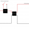
As requested some diagrams. Apologies for the amateur nature of these but I hope they demonstrate the issue well enough.

Circuit 1
Circuit1.png
In this circuit I have simply added in the Octocoupler into the existing record switch. In this scenario the record function doesn't work at all.

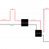
Circuit 2
Circuit2.png
In this circuit I am using the remote control switch circuit which requires the Adafruit soft latch as posted above so the momentary switch can act as on/off switch. In this scenario the circuit switches on but will not switch off.

I have tried reversing the circuits so that the battery cicruit is the controlling circuit but it makes no difference to the outcome.

Does anyone have any thoughts on this? Any help appreciated.
 

Fish4Fun

So long, and Thanks for all the Fish!
Hey Richard!

I was hoping your schematic would be a little more than it is .... but perhaps it is enough to start.... I am **assuming** the "red traces" are +3.3V ? I ask because (as counter intuitive as it might seem) typical, simple, low voltage switches.... switch ground and not Vcc. Not saying your devices are following this convention, but I would assume they are until I was certain they are not.

Next we need to separate the camcorder from the DVR... By this I mean you need to test the circuit on 1) the camcorder, 2) the DVR and only when it is working 100% on BOTH individually should you attempt to test the circuit on both simultaneously.

With that in mind ... beginning with the camcorder ... Does the momentary switch need to be "held on" while recording? OR do you "touch it on" and then some time later to stop you "touch it off"? Same question for the DVR. Before we can move forward, we need to make 100% certain how BOTH of these switches are designed to operate.

Next up will be determining if the switches are "Active High" or "Active Low". While your schematic seems to indicate "Active High" I strongly suspect both are "Active Low".

We are on different continents, so there is some lag in communication, I am sure that is frustrating, but it is important that you have a firm grasp on how these switches work before you attempt to modify them. No matter how simple you might think a switch is, before you can modify it, you really do have to know how it functions ... In Fact, I am pretty sure your troubles revolve around attempting to switch "Active High" .... ;-)

Good Luck!

Fish
 
Thank you very much for your reply. I do appreciate it must be hard reading. I am just getting to grips with all of this so thanks for taking the time to help me out.

Right so to answer your points. Both circuits work fine in isolation (by which I mean on their own - away from the optocoupler - I know they are still technically isolated with the optocoupler). The DVR one works well regardless of the optocoupler being involved - it seems the more forgiving of the two circuits.

So the problem circuit is the camcorder one. Just having the optocoupler in the circuit (without the DVR on the other side) is enough to cause issues. For circuit 1 there is no need to hold down the momentary switch. This circuit is the record button switch and as you might imagine is a press on / press off arrangement. But as soon as you introduce any other component into the circuit the switch fails to work - hence it could be the optcoupler or a resister, or multimeter (I was trying to measure the current going through but couldn't because the switch wouldn't work when I connected the multimeter). Therefore my thoughts are that this circuit is very precise when determining the current required to activate the switch. That's when I gave up and looked at circuit 2 instead.

Circuit 2 is the wired remote control circuit which you have to hold down to record from. I think the actual remote control would have had a soft latching circuit within it so that it would work in a press on / press off manner. Therefore I added in the Adafruit breakout which does achieve this in isolation but when the Optocoupler is added it will only press on, not off.

However I revisited this last evening and there was something I forgot to mention - for circuit 2 there is also a power rail. The power rail carries a higher current than the switch rail and I think could be the key to where I am going wrong. So we have three wires - power (~ 0.9A), switch (~0.1A) and ground. I really wish I had a remote control for this so I could see how the switching circuit is wired up. It's one of those early wired remotes with a 3.5 inch jack. This may be a common switching setup but obviously would be new to me so perhaps you could advise. I'm guessing the switching wire either shorts the circuit to activate the switch, or adds the extra power needed to operate the switch. I'm not sure how this fits with active high or active low.

It does seem that the optocoupler is perhaps causing a current drop sufficient to stop the switch from operating in both cases. I have ordered a couple of extra optocouplers just to see if they are less disruptive but obviously that is guesswork so any expert advice would be appreciated.

Anyway, I should have some time in the next few days to get some more accurate readings of the voltage and current levels if that would be useful.

Thanks again for your patience with me.
 

Fish4Fun

So long, and Thanks for all the Fish!
Hey Richard!

By "Active High" // "Active Low" I mean that the "on" state is signaled by Vcc or Ground. In Common Parlance a switch "powers on" a device seeming to suggest that the switch is controlling "Hot" // Vcc // V+ . This idea is reinforced by everyday experience with things like light switches .... To make a lamp glow, one turns on the switch which completes the circuit, and for safety reasons it is typically the "Hot" line that is switched ... in a different era it would be analogous to opening a gas valve to make a gas lantern glow .... Early scientists (somewhat arbitrarily) assigned "+" (positive) and "-" (negative) to represent "charge", and it was assumed that "charge" moved from "positive" to "negative" ... books were written, classes taught and conventions established .... and then reality came crashing in ... electrons are the movers and shakers responsible for both potential difference (voltage) AND Current (defined as the flow of electrons), and wouldn't you know it, the little buggers are negatively charged! So, to make something "Positively Charged", electrons must be removed ....

So, why the preamble on physics? Electronics is a subset of physics, like it or not, everything in electronics has to play by the rules defined by physics, and frequently to gain insight into common conventions in electronics it is easiest to step back and look at the roots.... In this case the "convention" of using "ground" to enable a circuit stems from the physics of electron movement and the switches employed to perform this task. The most basic and prolific switch in electronics is the transistor...

As a quick example read this:

https://en.wikipedia.org/wiki/Common_emitter

then a quick look at this:

https://en.wikipedia.org/wiki/Common_collector

In the case of the common emitter, the output is held "High" by a "Pull-Up" resistor .... when the switch is "enabled" the output is pulled to ground. Assuming the current through the pull-up resistor is negligible, the remaining current carrying capability of the switch can be delivered to the load. In the case of the common collector the output is held "Low" by a "Pull-Down" resistor, when the switch is turned on, the output is connected through the switch to Vcc. And, as long as we are dealing with Ideal switches in abstract circuits the possibilities seem fantastic! But Physics is a harsh landlord taxing her subjects with relentless precision....there are NO ideal switches. Engineers have spent the last 60 years designing and tweaking designs to improve the switching characteristic for particular purposes ... and we use a lot of them ... for instance a 16 GB flash drive contains roughly 64 billion transistors! But this does NOT imply you can introduce new functionality to an existing design by haphazardly introducing one more transistor (in this case an opto-coupler) .

On the list of things you have yet to mention (or show in your drawings) is the type of opto-coupler you are using nor how you have it configured. As an example of SOME of the various types of opto-couplers available look here:

http://www.nutsvolts.com/magazine/article/optocoupler-circuits

I suspect the voltage you have labeled "3.3V" is in reality the "Pull-Up" leading to the existing switch, and that the "momentary button press" pulls the output "Low" to start/stop the recording process ... I suspect that you are attempting to use this 3.3V "Pull-Up" to power the Emitter side of your opto-coupler and because of the emitters forward voltage drop it is inhibiting the camcorder's intrinsic functionality, but we seem to be having difficulty getting you to properly describe your circuit, so I am at a loss as how to instruct you. I need to know exactly what components you are using and how they are connected. I need you to test the "3.3V" from the camcorder when the record button is depressed to see if, in fact, it reads "0V" (or near (0V) when the button is depressed (Active Low switch).

Until we determine if the switch is "Active Low", there is little I can offer except anecdotes :)


Good Luck!

Fish
 
Hello again,

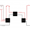
Thanks again for taking the time to go through this. There is clearly a lot to learn. I have now taken some measurements and below are some updated diagrams. As before the first is using the record button circuit and the second is the remote control circuit.
Circuit1.png
Circuit2.png
Some voltage measurements are missing. Apologies, I can get these to you if need be. Anyhow it would appear that the current in these circuits is very small. It would therefore appear that the issue may well be that the Optocoupler is providing too much resistance to sit comfortably in the circuit, and hence everything seems to break when the the Optocoupler is introduced. In the case of the power circuit this is very precise and as I said before, the switch stops working when any other element is introduced into the circuit, to such an extent that when I added in the multimeter to measure the current the switch stopped operating. The multimeter read 477 microamps before the Optocoupler and around 300 after the Optocoupler was added so I suspect it needs 500 microamps to work. For the record it only recorded current when the button was pressed so does that make it active high?

Anyway it would be useful to find out if my theory is correct but the only way to do this would be to increase the current flow through the circuit. One thing I do understand is Ohms Law so I guess if I could decrease the resistance or increase the voltage I could see if this makes a difference. However as the circuit is part of the main Camcorder circuitry I really don't want to mess around with this so the former is not an option. Is there a safe way to increase the voltage in circuit 1 above?

I have tried using different Optocouplers. I have most types. The ones that appear to work best are the two pins ones such as this: https://www.maplin.co.uk/p/low-current-opto-coupler-cy94c which are geared for low current but I guess my current is too low. Is there a Optocoupler or similar component that would work with < 1 ma current and provide what I need?

Thanks once again.
 
Top