Hello all,
I would like a schematic to breadboard tutorial with clear pictures and explanation for an American traffic light system, light duration times are not that important to me, Red stays on for say approx 1 minute then goes immediately to green, stays on say a minute, then goes to yellow, for say 15 seconds, as warning, then back to red then repeat all over again.
I found many for the UK traffic lights and got confused transferring to breadboard.
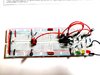
I am new to electronics, it's a hobby for me. I am not clear on how to go from schematic to breadboard, making the connections, with the wires. I get confused.
Can anyone help me understand how to hookup the wire to the breadboard just by looking at the schematic.
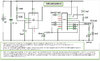
I would like to use these components and here is the schematic too. See attachment
I would like a schematic to breadboard tutorial with clear pictures and explanation for an American traffic light system, light duration times are not that important to me, Red stays on for say approx 1 minute then goes immediately to green, stays on say a minute, then goes to yellow, for say 15 seconds, as warning, then back to red then repeat all over again.
I found many for the UK traffic lights and got confused transferring to breadboard.
I am new to electronics, it's a hobby for me. I am not clear on how to go from schematic to breadboard, making the connections, with the wires. I get confused.
Can anyone help me understand how to hookup the wire to the breadboard just by looking at the schematic.
I would like to use these components and here is the schematic too. See attachment
- 1x NE555 IC
- 1x CD4017 counter IC
- 1x 10uF Capacitor
- 1x 0.1uF Capacitor
- 3x LEDs (Red, Yellow/Orange, Green)
- 3x 100 ohm Resistors
- 2x 100K Resistors
- 1x 22K Resistor
- 6x IN4007 or 1n4148 Diodes
")