I am looking to educate myself on electronics. I know the very basics (the function and symbols for most components) and can build things given a set of schematics, but I feel a bit lost designing my own.
I'm more a a visual learner so I like things that teach with pictures and diagrams rather than lengthy paragraphs. I also like stuff that gets straight to the point without a lot of needless filler.
If you guys could recommend some books or websites you think would be helpful to someone like myself I would greatly appreciate it.
The reason for this sudden desire to learn electronics is that I'm in the process of designing some circuitry for a project (it's kinda secret for the moment) I'm working on which should be pretty simple, but I'm a little confused about some parts of it. I also don't know the exact size of the motor I'm going to need yet so I'm kinda in the dark about how much amperage the circuit will need to be able to handle (shouldn't be too much though).
Eventually, I also plan to "digitally" control this project with micro controllers, but I'm saving that big hurdle of learning until after I get it working with more "analog" trigger.
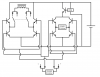
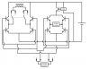
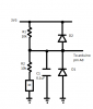
If there's anyone that would like to have a look at the circuitry I'm thinking up and give me some pointers I'll try to draw it up on Photoshop (unless someone can recommend a better (free) program for making schematics).
Looking forward to picking your minds!
Rhett
I'm more a a visual learner so I like things that teach with pictures and diagrams rather than lengthy paragraphs. I also like stuff that gets straight to the point without a lot of needless filler.
If you guys could recommend some books or websites you think would be helpful to someone like myself I would greatly appreciate it.
The reason for this sudden desire to learn electronics is that I'm in the process of designing some circuitry for a project (it's kinda secret for the moment) I'm working on which should be pretty simple, but I'm a little confused about some parts of it. I also don't know the exact size of the motor I'm going to need yet so I'm kinda in the dark about how much amperage the circuit will need to be able to handle (shouldn't be too much though).
Eventually, I also plan to "digitally" control this project with micro controllers, but I'm saving that big hurdle of learning until after I get it working with more "analog" trigger.
If there's anyone that would like to have a look at the circuitry I'm thinking up and give me some pointers I'll try to draw it up on Photoshop (unless someone can recommend a better (free) program for making schematics).
Looking forward to picking your minds!
Rhett
")