Maker Pro
Maker Pro

Need to understand the functioning of this circuit.It is Charge controller..

I have attached the image of the circuit here. Please any one help in understanding it. Thnks :)
 

Attachments

  • 8051 based solar charge controller.png
    8051 based solar charge controller.png
    56.9 KB · Views: 6,788

Harald Kapp

Moderator
Moderator
Where did you take that image from? There should be a description on the website.

Some basic functions I identified:
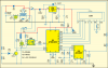
1) 7805 generates a 5V supply voltage for the circuit from 12V battery voltage.
2) ADC8031 measures the voltage of the battery.
3) IC3 and T3 form an isolated driver tu turn on or off the load.
ZD1 and T1 is an overvoltage detector for the voltage from the solar panel. If the voltage on the panel is greater than approx. 16V (note the divider R8/R9) pin P3.4 of the µC receives a low signal. Otherwise high level.
4) IC1 does alll the controlling. You need the description or (better) the source code for the software running on IC1 to understand what the circuit does.
5) Switches, pushbuttons, LCD - obvious.

Harald
 
I have the code but its very advanced so i m not able to understand it and website from where i took this image just described the feature of the circuit and nothing else :(
 

Attachments

  • Solar.zip
    7.4 KB · Views: 271

Harald Kapp

Moderator
Moderator
Sorry, but I will not analyze 33k of assembler code listing. Specially as it is only sparsely commented and no description of the overall working is given.

Have you tried to contact the publisher of the circuit/code?
 
Hey, I wanted to know how BS170 is working in the circuit mentioned before and can anyone provide me the link to its datasheet. Google is showing different kind of BS170 and i am confused which one is used here.
 

Harald Kapp

Moderator
Moderator
You could have asked that in the first place.

BS170 is an n-channel MOSFET. It is driven by the µC's pin 3.5 at the gate. If the gate is low, the transistor is open, the relay is de-energized and the NC contact (normally closed) is connected (as shown in the diagram).
If the gate is high, the relay is energized and the NC contact is open (inverse position to the diagram).
 
I am not able to understand when gate is high how relay is energised and how current is going to flow through relay. Since there is a zener diode there so current can only flow from solar panel to battery but how current can flow in this direction.
 

Harald Kapp

Moderator
Moderator
Since there is a zener diode there so current can only flow from solar panel to battery but how current can flow in this direction.
Which zener diode do you refer to? D1...D4 are standard diodes and you can't possibly mean ZD1, do you?

The relay coil is connected to the battery's + pole and to the transistor. If the transistor is on (gate = high) the the other pin of the relay coil is connected to ground. Thus a closed circuit from battery "+" <>coil <> transistor <> battery "-" is created and the relay is operated.
 
Last edited:
Yes I think you are right. I was confused with this diode inside the BS170 which will allow current only from source to drain. You have to see it carefully. In, BS170 you will see there is a diode probably zener diode which will block current from drain to source. That is confusing me.
 

Harald Kapp

Moderator
Moderator
The diode within the MOSFET is the body diode which is automatically generated due to the structure of the MOSFET. It is of no importance here.

Harald
 
Top