Maker Pro
Maker Pro

Need to know pin out (input output voltage ) of an old UPS Transformer

I have an old ups transformer, brand name is missing with ups cover box. This ups was operating in 220~230v input. I am uploading an image of this transformer, I need to know how to identify input voltage (primary cable) and output voltage ratings of other cables.
a9590c9a85.jpg


Please help.
 

(*steve*)

¡sǝpodᴉʇuɐ ǝɥʇ ɹɐǝɥd
Moderator
Well... Use a multimeter to determine which belong to the same windings. There are multiple possibilities.

Then take the pair of wires with the highest resistance between them and apply 12VAC to them (that's 12, not 120, 240, etc!!!). Once you have that connected, measure the voltages on the other windings. This will give you the ratio of the windings to each other.

WARNING Connect your multimeter before you apply the 12VAC. If you made a mistake you could have dangerous voltages!
 
Sir Prohor . . . . . . .

In initially examining the accumulated layer of iron oxide on that one particularly affected E lamination.
In its highest level of oxide deposition . . . .as is being verified with a scanning electron microscope . . .is showing right at a 473 micron height.
THIS transformer then would date out as being of about a 1998 vintage . . .18 years old . . . . with a variable thrown in by any subjective long time humidity averaging being experienced..

Now with the additional input from some of youse You-are-a peein' guys on 230 V . . . on . . . . . . wiring color coding scheme.***

Does it not look to you, that the AC power line input connection would be related to the BLACK-BROWN-RED wires to the right side of the photo.*** With Black being the NEUTRAL connection and and then an optional LIVE wire connection to either BROWN for 240VAC input or RED for 220VAC input . ( I may have guesstimated / assigned the last two colors backwards). But an ohms test between the RED and BROWN wires would reveal but a fraction of the resistance reading between BLACK . . . to . . . . . RED or BROWN.

That leaves the YELLOW-BLUE-YELLOW wiring to be for the Low Voltage AC supply to be rectified to feed the units storage battery, with BLUE being its centertap.

Then you go to the back side of the transformer and select out the two RED's and WHITE-BLUE as being the two pairs of windings that receive the drive from POWER Transistors, FETS or IGBP Transistors, that are then powered up at the loss of AC line power coming in to the primary winding of this power transformer.

Now . . . . Prohor . . . . take ohmmeter in hand and go test out those wires to see if windings + wire colors agree with those supposed wire colors versus winding functions.

73's de Edd
 
Last edited by a moderator:
Well... Use a multimeter to determine which belong to the same windings. There are multiple possibilities.

Then take the pair of wires with the highest resistance between them and apply 12VAC to them (that's 12, not 120, 240, etc!!!). Once you have that connected, measure the voltages on the other windings. This will give you the ratio of the windings to each other.

WARNING Connect your multimeter before you apply the 12VAC. If you made a mistake you could have dangerous voltages!

Dear Steve, I was trying these steps before posting this thread but was not sure. At that time I used 5v AC instead 12 v, what confused me that time is from one side To other I got very little change when I was expecting to get a major change as it shoud voltage step down or up!
But thanks a lot as I know steps you suggested should be enough to find my requirements. It is important for my students to save them from wrong direction.
Thanks again.
 
Sir Prohor . . . . . . .

In initially examining the accumulated layer of iron oxide on that one particularly affected E lamination.
In its highest level of oxide deposition . . . .as is being verified with a scanning electron microscope . . .is showing right at a 473 micron height.
THIS transformer then would date out as being of about a 1998 vintage . . .18 years old . . . . with a variable thrown in by any subjective long time humidity averaging being experienced..

Now with the additional input from some of youse You-are-a peein' guys on 230 V . . . on . . . . . . wiring color coding scheme.***

Does it not look to you, that the AC power line input connection would be related to the BLACK-BROWN-RED wires to the right side of the photo.*** With Black being the NEUTRAL connection and and then an optional LIVE wire connection to either BROWN for 240VAC input or RED for 220VAC input . ( I may have guesstimated / assigned the last two colors backwards). But an ohms test between the RED and BROWN wires would reveal but a fraction of the resistance reading between BLACK . . . to . . . . . RED or BROWN.

That leaves the YELLOW-BLUE-YELLOW wiring to be for the Low Voltage AC supply to be rectified to feed the units storage battery, with BLUE being its centertap.

Then you go to the back side of the transformer and select out the two RED's and WHITE-BLUE as being the two pairs of windings that receive the drive from POWER Transistors, FETS or IGBP Transistors, that are then powered up at the loss of AC line power coming in to the primary winding of this power transformer.

Now . . . . Prohor . . . . take ohmmeter in hand and go test out those wires to see if windings + wire colors agree with those supposed wire colors versus winding functions.

73's de Edd

Dear 73's de Edd,
You
are right, It is very old I got this UPS around 2001/2002, I can not remember. I will check back again in my lab.
Your information will help me too and I will check as you advised.

Thanks for your help, I think I will be able to help my students in this case although I do not teach this subjects to them. I was just involved thinking that their procedure testing with higher voltage was wrong and very dangerous.
Thanks again.
 
Last edited by a moderator:
Sir Prohor. . . . . . .

Once your guys have zeroed in on the wires that go to specific windings by ohmming tests, I feel that the AC line input that I mentioned will fall into place. Just confirm my assumption of there being a higher/lower line voltage option.
HECK . . . . there ? might ? even be a 220VAC or 120VAC option on that winding.

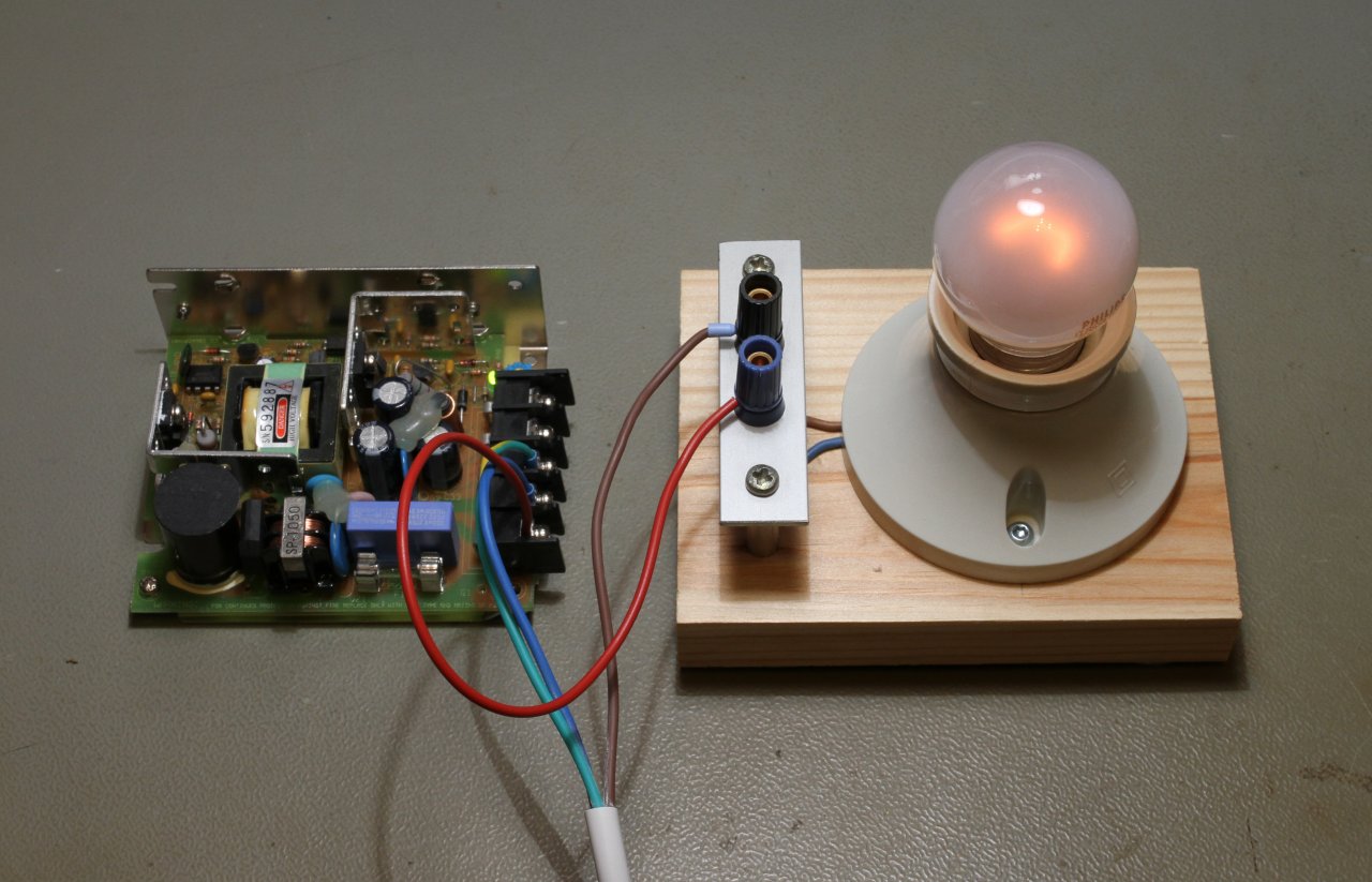
The next safe manner of testing will be to use an incandescent lamp in series with your AC Line input voltage.
Higher wattages of different lamps screwed in will let progressively more power pass through, but initially use a 40-60 watt unit.
THEN any grossly excessive power consumption will be transitioned into making a BRIGHT, light while the tested / load circuitry is then being power starved and thereby . . . . . protecting it.

That series lamp will still let your transformer core activate to a high enough level of saturation to produce voltages on the then unloaded secondary windings.
You then AC meter them, with most initial interest on the battery charge supply winding, and then the separate solid state drive input set of windings, which will probably fall in around the 12VAC range.

A Power Limiting Test Lamp . . . .for safer initial power ups . . . . it's got your back (and wallet) . . . . babe

lightbulb-trick-large.jpg


73's de Edd
 
Last edited by a moderator:
Top