Maker Pro
Maker Pro

Need help with Wien-Bridge Oscillator

Greetings everyone, i have a assigment and i need to create a wien bridge oscillator that uses potentiometers so the out freq can be modified between (10, 14 )kHz...and the out voltage between (6,9) V ... i already made a sketch but i just cant figure out how to do this...every time i try to make the amplitude bigger the frequency changes and the other way around. Please, can someone help me ?
 

Attachments

  • 14k HZ---8V.jpg
    14k HZ---8V.jpg
    94.5 KB · Views: 383
Last edited by a moderator:

Harald Kapp

Moderator
Moderator
Welcome on the forum.

1) I moved this thread to the homework section.

2) A Wien bridge is a rather delicate thing. Separate the two tasks (setting frequency and setting amplitude) into two sub-circuits.
Build the Wien bridge oscillator with adjustable frequency (changing R1 and R2 simultaneously will require a stereo potentiometer).
Add an amplifier to decouple the oscillator from the load and to adjust the amplitude independently from the frequency.
 
Thanks Harald Kapp for your reply. I didnt add any potentiometers since i didnt really know where to put them ...could you please make a quick sketch on how to place the 2 op ams?...dosent have to be exactly just a quick paint sketch so i get a basic ideea cause im preety lost here
 

Harald Kapp

Moderator
Moderator
To change the frequency you change R1 and R2 or C1 and c2. Changing R is a lot easier. So use a linear stereo potentiometer instead of R1 and R2.
See this tutorial on Wien bridge oscillators.


You already have marked the output of the oscillator with a green pin.
Add any flavour of amplifier at this point. I suggest you use a noninverting circuit (the link shows the circuit diagram).
 
so you are saying i should use the first immage i attached
osc27.gif
and replace the rezistances on the wien bridge with potentiometers to change the frecvency and then use the other amp(img2) in series with the wien bridge amp and there change the amplitude of the sine waves?
opamp15.gif
 

Harald Kapp

Moderator
Moderator
Exactly- Vout of the Oscillator is Vin to the amplifier.
Use a potentiometer in place of R2 and Rf of the amplifier to adjust gain (>=1). If you need gain <1, insert an attenuator (resistive voltage divider) between the two circuits.

Note that you will need some kind of stabilization for the oscillator to output a reasonable clear sine wave. Often a simple incandescent lamp is used, as in this example.
Otherwise the oscillator wil stop oscillating if the feedback is to small, or will distort the signal if feedback is too high. You can't reliably set resistors R1 and R2 of the oscillator to perform equally well across all possible circuit variations (temperature, supply voltage etc.)
 
Harald Kapp , u saved my life man, dont know what i would have done without your help...ill try to finish the circuit as soon as possible and post it here, but probably tomorrow. Danke schon!:D
 

Harald Kapp

Moderator
Moderator
What exactly do you mean by "not so precise"?
Frequency, waveform, amplitude?

The diodes in the feedback path introduce quite some nonlinearity. The lamp based circuit is well proven (it was used, if not invented) by Hewlett-Packard in their instruments - and those are renowned for their quality.
 
Nooo, the wave form is ok its just that i dont get 6 V i get 6,1 V or so... but its ok i dont need it to be that precise...so, could you asses my work? is it any good?:D
 
By changing only one potentiometer (R) it is also possible to change frequency, but not linearly. The tandem pot is no strictly required, but that's a more elegant way to do it.
 
by giving this values to the potentiometers in the first ao, whenever i max the potentiometer (value=1) i get the lowest frequency but to make it 14 khz the highest frequency i need i have to turn the value to 0.65 ....how can i make the potentiometer value to be 0=14khz ...value=1 ...10khz ?
 

Harald Kapp

Moderator
Moderator
Since your pot is 13k, you vary between 1*13k=13k and 0.65*13k=8.45k.
Therefore you can replace the pot by a fixed resistor of 8.45 plus a potentiometer of 4.55k.
Practical values could be 9.25k (from the E96 series) for the fixed resistor and 4.7k for the potentiometer.
 
Hey guys...its me again
I really need your help...iv finished my design only to find out that my total harmonic distorsions are 60%!
can someone please help me reduce the harmonic distorsions?
here is a picture of my circuit
final_zps17ffdce4.png
 

(*steve*)

¡sǝpodᴉʇuɐ ǝɥʇ ɹɐǝɥd
Moderator
Do you have an oscilloscope?

What does the signal look like at the three points you have marked?

Why do you have that buffer between the oscillator and the amplifier?
 
Disclaimer: I'm not particularly knowledgable about this stuff and I'm just speaking from experience of my own dabblings.

Diode stablisation works well if you catch it right at the point where they begin to conduct. Replace R12 and R8 with a variable resistor and you'll be able to hear the difference from a smooth sine wave when it begins to oscillate to the distortion. It puts a strict limit on the output voltage so I would recommend putting a buffer there to counteract any loading from the second amp stage.
 

(*steve*)

¡sǝpodᴉʇuɐ ǝɥʇ ɹɐǝɥd
Moderator
Here is something you should read.

As I have suggested, an oscilloscope is required. It describes how both a lamp stabilised and diode stabilised wien bridge oscillators are set up for minimum distortion.
 

(*steve*)

¡sǝpodᴉʇuɐ ǝɥʇ ɹɐǝɥd
Moderator
Just for fun, I decided to characterize a few bulbs I have and t use one to build a wien bridge oscillator.

I have 3 small bulbs. They are, 5V 60mA, 6V 40mA, and 12V ("grain of wheat") bulbs.

I connected a voltmeter in parallel and an ammeter in series to measure the voltage/current over a range similar to what I might expect to find in this circuit.

As it turns out, the graphs look surprisingly similar, so here are the graphs of the bulb I eventually used (the 12V grain of wheat bulb).

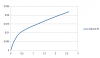
First is the raw Voltage vs current graph:

attachment.php


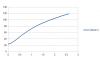
Next, the more useful voltage vs resistance graph:

attachment.php


So, I build a circuit like this:

attachment.php


For my circuit R1 = R2 = 5k9, C1 = C2 = 47n, and R3 = 100R. The op-amp was a 741.

The frequency is calculated as being around 573Hz.

R3 was chosen so that (R3 + RL)/RL woud be greater than 3 with a cold lamp, and equal to three at a sensible amplitude (which turns out to be between .25 and .75 VRMS).

I picked 100R because that gives a gain of about 5 when cold, and a gain of about 3 with a resistance of 50 ohms (or just over 0.5VRMS)

And so I built it:

attachment.php


Not really exciting. Note that you can't see any glow from the bulb.

And the output looks like this:

attachment.php


The upper trace is from the the oscillator, the bottom one from a signal generator at close to the same frequency (around 575Hz).

The top trace is about 4V peak to peak. That suggests the voltage across the bulb is about 1.333 V ptp. And that's about 0.47VRMS, which is a little lower than expected.

This image was taken after the oscillator stabilised. After power is applied, it can take 10 seconds or so before the output settles down. The instability is in the form of amplitude variation.

I don't have anything to measure the distortion of this sine wave, but It looks pretty good to me, and much less than 60%! :)
 

Attachments

  • 12V-VI.png
    12V-VI.png
    9.6 KB · Views: 800
  • 12V-VR.png
    12V-VR.png
    9.4 KB · Views: 758
  • Wien-Bridge-basic-lamp.gif
    Wien-Bridge-basic-lamp.gif
    2.3 KB · Views: 924
  • IMG_4845b (Small).JPG
    IMG_4845b (Small).JPG
    37.9 KB · Views: 746
  • IMG_4846b (Small).JPG
    IMG_4846b (Small).JPG
    89.2 KB · Views: 685
Last edited:
Top