Maker Pro
Maker Pro

NEED HELP Troubleshooting Sole f63 2016 model *will not power up*

Sole Treadmill Will Not Power Up
Model: F63
Rating: 120Vac, 60 Hz, 12 A
Date Code: 2016, 1Q
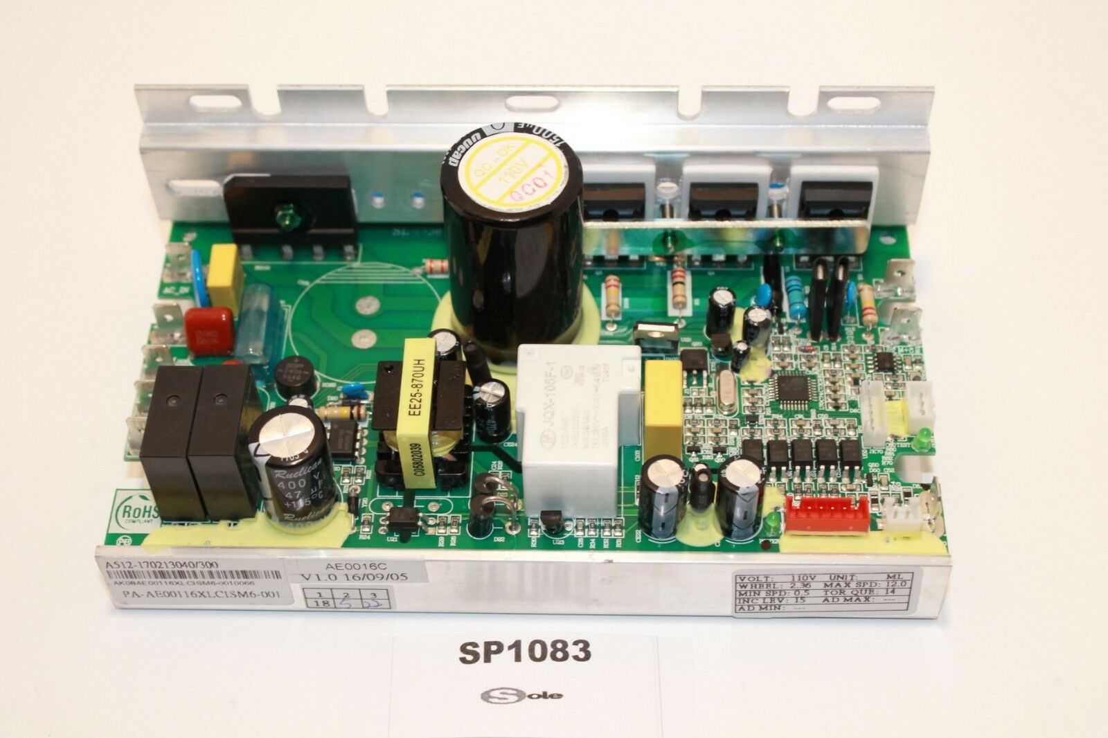
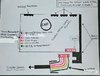
Lower Motor Control Board Info:
A512-151128010/1850
BI50AE116XLCISM6-0011558
PA-AE00116XLCISM6-001

AE0016C
V1.0 15/12/29
*Note* My LMCB has a Red colored connection on both the LMCB itself & the wire harness (red connector has 6 wires total) going to the display.

I have tested the Motor while using a 18v DC Battery from a drill. It ran smooth. The Red LED power light on the LMCB it lit up & solid but the display does not work. I can't find any troubleshooting info on the web that's specific to my LMCB. Also the boards with the 6-wire Red connector is double the price as the ones with the 12-wire White connector. Would really appreciate some help troubleshooting this problem. I'm pretty certain the big Cap in the middle of the LMCB needs to be replaced.
*I tried attaching pictures but kept getting a pop-up telling me error the file could not be uploaded*
 
Sir Spidyymannn8 . . . . . . . . . . . . ( I has not done yets . . . ever remember of having been meetings a Spideyman ! . . . . . . .
. . . . . . . . . . . . . . . . . . . . . . . . . . . . even with his being at 7 full stages of digression. )

Your photo must be exceeding the bit density limits of this sites requirements.
In the interim, see if the only unit that I found, that was using one sole RED connector, happens to be your unit.
If so, i can already see some good possibilities showing on it.
HEREWITH . . . .

s-l1600.jpg


73's de Edd . . . . . .


Why . . . . I now ask anyone . . . . WHY ? . . . . . . is it, that I always seem to buy the plants at the nursery, that just don't have the will to live?


Last edited:
I have just repaired a Sole F63 treadmill which when switched on did initialise but then failed to start the belt motor.
The motor controller pcb is the type with one 680uF cap and a 12-pin control cable to the console.


R0019829.jpg


Eventually this was traced to two causes: 1) a blown solder joint between the relay (there is only one on the board) output pin and the pcb track & 2) a faulty reed relay speed detector.
The pcb had to be removed from the Aluminium heat-sink by carefully cutting the adhesive holding it in the slots to get at the solder side.
A spare reed relay hack and cleaning up and re-soldering the joint got it working OK.
My next problem however is to sort out the connections for a speed-control potentiometer to be fitted to the board so that I can use it to power a bandsaw. I could then ditch all the extra paraphernalia, such as the console, soft-start, lift motor, etc to hopefully end up with just a variable speed dc motor.
I've searched the web for a circuit schematic diagram, but Sole keep things tightly controlled (?)
If anyone has ideas of where to look I'd be grateful.
 
The pcb is laid out for a number of different versions but only equipped with components for the 'Sole F63' treadmill. As mentioned earlier, the controller now works correctly in all respects.
What I need is a circuit schematic diagram or details of how to add a speed control pot to the pcb and dispense with the unnecessary functions.
 
73's de Edd The photo of the motor control board you posted is indeed the same one that my unit uses, the only difference that I see between mine and the one you posted. My RED connector actually only has 5 pins sticking up from the LMCB, the very few I have seen online seems to have 6 pins on the Red Connector which would make sense because that main wire harness does indeed have 6 wires. The Red connector was glued in because I had to cut the glue away to be able to remove that Red Connector. The other thing is above the Red connector is a set of 5 square black 4 legged components and my board only has 4. Since I just recently acquired this Treadmill i cannot confirm that this is how it was before and since there is very few for sale online to compare to its hard to say that those 2 things are supposed to be there.
Thanks to everyone that suggested the pictures being too big and over the limit. This is really my first Forum post ever and very new to how it all works so please bare with me and any help/hints to how to navigate this site.
 

Attachments

  • 2.jpg
    2.jpg
    297.8 KB · Views: 16
  • 3.jpg
    3.jpg
    414 KB · Views: 18
Also I don't know if I said anything about the big Cap in the middle of the board that has a burnt markings or brown discoloration. I have a ESR meter and that is the reason I took the board out of the Treadmill was to test the Caps but that is when I noticed that it wasn't that easy to access the back side of the board. Side Question concerning the Thermal Paste that is used on the Bridge Rectifier and the other 3 components. Would any kind of Thermal Paste due? I have some from replacing my CPU on my Laptop but I couldn't find an answer from googling what is the best Thermal Compound to use in this situation.
 

Attachments

  • 1.1.jpg
    1.1.jpg
    200 KB · Views: 15
  • 2.2.jpg
    2.2.jpg
    403.8 KB · Views: 15
That one leg of D24 looks as if heat unsoldered it. And the track has burned. Check for continuity between that leg and the other end where that track goes.
 
The other end, closest to big cap
I checked for continuity from the D24 component from the end closest to the big Cap and I was able to get continuity from there to where the trace led to. So the solder joint must be good. I also checked for continuity. In the main 6 wire harness that goes to the Red connector and every wire tested good. I called Sole Tech Support yesterday and they did absolutely no troubleshooting besides telling me that I should replace the main harness due to the reason its what communicates with the display.
 
Maybe check the connectors of the 6 wire harness to make quite sure there is connectivity
I will double check. Do you by a chance know anything about testing Bridge Rectifiers? I noticed when checking the AC side it gradually climbed in volts. Is that normal?
 
Last edited:
Maybe check the connectors of the 6 wire harness to make quite sure there is connectivity
I can't really check the connectivity of the 6-wire harness without taking the board off the heatsink. Also would have to remove the console display board to be able to check connectivity in the 6-wire connector
 
Hmmm. AC side is your house voltage. Not normal
· When I checked the VAC [middle pins] of the Bridge Rectifier it slowly climbed to ~118VAC after I supplied power.
· The outside VDC pins measured 15VDC
· Also tested the LMCB Motor connection pins & measured 62.3VDC
· Also tested each pin of the Red connector on the LMCB with the 6-wire harness unplugged, aslo with it plugged in but then testing @ the end of the 6-wire harness on the Display Console side. I will attach a picture with the readings shortly, both measurements @ LMCB & Display Console were pretty much the same. The results never were steady & all the measurements were taken in VDC W/black test lead on the black/ground of the Red connector/6-wire harness.
I should say I'm not the best at this troubleshooting stuff or even know if I'm doing things correctly, so if something ever doesn't make sense or doesn't seem right let me know if there is something I need to do again or differently
 
That 6 wire harness is used to connect 1 component to another component. Can you find the first component downstream of the first wire,that is your first reference point. Now go to the other end of the first wire and find the first point it connects to. That is your second reference point. Now connect a multimeter in continuity/diode mode between those 2 reference points and check for continuity. Repeat for other 4 cables. If all checks good the cable is not the problem.
Also a good idea to wiggle the harness while checking each cable in case there is intermittent connection

I did recheck the Bridge Rectifier and I must of did something wrong the first time. so the AC input voltage is at about 115v and the DC output voltage is 146v. After unplugging it I checked for warmth anywhere and also was using a infrared temp gun while it was powered on and didn't get any red flags either way. I also checked the 6-pin wire harness and that is definitely good as well as I checked the wire connector on the MCB and the Control display board, each pin separately to make sure it has Continuity to somewhere close on both boards whiles it was unplugged and plugged in.

I guess I will take the Heatsink off the board and check the big Cap as well as the others with my ESR meter. I also checked the Bridge Rectifier in Diode mode and it tested good.

I don't know what else to really do :-( Oh Ya the last thing I noticed is when I had the 6-wire harness unplugged from the display console board the LED light on the MCB got brighter as well as more steady/constant. When I plugged the 6-wire harness back into the display console board the LED dimmed and I guess it has a little fluceration in the brightness, it doesn't blink but kinda dims if that makes sense. The only thing I can't think of is that the 6-wire harnesses RED connector on the MCB that has the "Potentially" missing pin which is to the GREEN wire of the harness is actually not supposed to be missing and that the previous owner messed with the board and didn't realize the pin was missing. It was glued in when i removed it so unless the previous owner reglued it back in place, I don't know.
 
Top