Maker Pro
Maker Pro

Need help to find output of board

Hi
I got board from store room don't have user manual/documents I am trying to understand connection of board

I have attached three picture
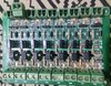
  1. First picture, when I give the 5v input to board one red led is turning on the board
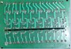
  2. Second picture show front side of board
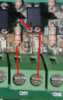
  3. Third picture show the layout of circuit
PC817 four pin IC
BD140 is transistor

How to make connection for output to check that board is working or not working?

5V signal.jpg
 

Attachments

  • front side.jpg
    front side.jpg
    193.1 KB · Views: 25
  • Back side.jpg
    Back side.jpg
    155.9 KB · Views: 23
That board is probably just a "opto isolated relay card" - but with a transistor output instead of relays.
What box did you pick it out of?

This card should not be hard to draw up schematic for one of the channels.
 

bertus

Moderator
Hello,

The PC817 chips are optocouplers.
The BD140 is a PNP medium power transistor.

Bertus
 

Attachments

  • PC817 Series.pdf
    103.1 KB · Views: 0
  • bd136-bd138-bd140_ON.pdf
    37.9 KB · Views: 2
Looks like water has caused some bad corrosion.

I can't say for sure unless you draw the circuit with resistor values, but it looks like the diode cathodes go to left side of op terminals and the transistor emitter (positive output) goes past the suitcase jumper (may be used to select either 3.3 or 5v?) and continues on to the other op terminal (+)on the right.

It appears to be a sourcing output where you would hook up (+) op terminal to your load, (perhaps a light bulb) and the neg side of your load would go to a negative power supply (likely 5v)and the positive of that power supply would go to the common terminal on the left.

The input should make the optocoupler feed the transistor base to switch it on.

It may even work with a continuity tester with at least 3 volts supply across the op terminals provided polarity is correct.

Try experimenting with a small lamp, battery and suitcase positions.
 
The card with the LED is most probably a micro controller board. It kind of looks like a remote controlled garage door control assembly.

The card with the opto's and transistors is a driver card for bigger loads .
 

Harald Kapp

Moderator
Moderator
Your images are not detailed enough for an analysis. As @Kabelsalat mentioned, draw a circut diagram from one of the channels. Should be relatively easy.

From what I can see:
  1. It looks like the screw terminals are the inputs. Pins 1 and 2 of the optocoupler are typically the LED pins, the resistor in series limits current. The separate SMD LED and resistor are there to indicate an active input:
    upload_2020-11-6_8-33-31.png
  2. The plug terminals then would be the outputs.
  3. The optocouplers will drive the DB140 transistors for more powre.
    upload_2020-11-6_8-38-26.png

Draw the schematic and you will see that it is a relatively simple circuit.
 

Attachments

  • upload_2020-11-6_8-33-25.png
    upload_2020-11-6_8-33-25.png
    88.4 KB · Views: 3
Hi
thanks for the many of help

I have separate PC817 IC and BD139 is transistor so I would like to make my own

Does this circuit make any sense to turn on the led with BD139. if its look fine than I will connect all on the breadboard to see result

upload_2020-11-6_4-5-51.png
 

Harald Kapp

Moderator
Moderator
Does this circuit make any sense to turn on the led with BD139.
50 %.
Where`s the optocoupler in this circuit? As shown, the 1 kΩ resistor ties the base to GND and the transistor will be permanently off.
That is not the trace of the output board we requested.
 

bertus

Moderator
Hello,

In your openings post you stated the transistors are BD140.
Now you say they are BD139.
Wich is correct?

Bertus
 

Attachments

  • bd135-bd137-bd139_ON.pdf
    37.9 KB · Views: 1
50 %.
Where`s the optocoupler in this circuit? As shown, the 1 kΩ resistor ties the base to GND and the transistor will be permanently off.
That is not the trace of the output board we requested.
That was only half portion, Here is complete circuit diagram

upload_2020-11-6_4-48-49.png

Hello,

In your openings post you stated the transistors are BD140.
Now you say they are BD139.
Wich is correct?
Hi Bertus
BD140 is on the board and I have BD139 on hand that I want to use to make circuit on breadboard
 

bertus

Moderator
Hello,

So the board circuits must be different, as a PNP has other control as the NPN transistors.

Bertus
 
Hello,

So the board circuits must be different, as a PNP has other control as the NPN transistors.
Correct, BD139 is NPN transistors and BD140 is PNP transistor

I believe my circuit is correct so should I make the connection on breadboard?
 

Harald Kapp

Moderator
Moderator
The circuit in post #10 looks correct. However, the label on the pcb in the first post says BD140. What is actually printed on the transistors?
 
Top