Maker Pro
Maker Pro

Need help identifying part

Greetings,

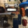
My mom has a Dacor RV36s stove top which has a vent that rises from the counter. After raising the vent the suction seemed weak, the control would not respond to set the fan speeds nor would it retract. No prior issues. I pulled the board and noticed a burn mark on the board. Having done some small projects and repairs in the past I thought I'd see if I could fix it vs the $150 for a new board. However, I can not identify the part which has the burns surrounding it.
Any help would be greatly appreciated.image.jpegimage.jpeg
 
I know, I know! That is a zero ohm link resistor (single black band), specifically a flame proof zero ohm resistor. There may be a problem elsewhere, or your resistor may be to fault. I think that the resistor is dodgy, as a good resistor of this type would probably be difficult to blow unless shorted straight across a supply. It is possible that the resistor was dodgy in the first place, giving a less than desirable resistance, as it was subjected to current, it possibly heated, raising it's resistance further causing it dissipate an undesirable power level. Alternatively, a power spike from a faulty power supply could be the problem causer, and fused the resistor with a power surge.

I suggest you try a zero ohm flame proof of similar size in it's place.

Also, provide more photos of the board.

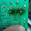
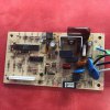
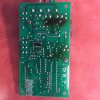
Thank you so much for the reply! Still a bit confused on why it only has two bands. Here's a couple more pics, I should have also noted that there is a diode that also has burn marks on it. Here's some more pics of the board. Thanks again
image.jpeg image.jpeg
 

davenn

Moderator
I know, I know! That is a zero ohm link resistor (single black band), specifically a flame proof zero ohm resistor.

I seriously doubt that !!! there is obviously more than a single black band
I can see a yellow one as well

the other colour bands have just been cooked off

@Warhawk have you actually removed the resistor and tried measuring it with a multimeter ?

if not you should
 
Sir Warhawk . . . . . . .

Ohhhh Tayyyy . . . I have us all started up now, but will need some feed back on parts and readings.

I have seen your HOT running metal "filumum" resistor on three different Pee Cee Bee pictures, as what looks to be either a 470 ohms or Sir Marduks 560 0hm . . . . . so we are waiting for your resistance measurement to estimate what it probably is being..

Either value would readily heat up, such as this one has done , while a 47 or 56 ohm or 4.7k or 5.6 k would be out of range of this cause and effect, with the voltage level involved.

Also I started on some parts placements overlays to the 3rd pic over while leaving the 2nd and 4th ones free, for unobstructed parts or foil path viewing / comparison.

Need an answer on all of my BLUE entrys:
(That's easy with using a CUT n' PASTE and then answer each, just below.)

On some of the boards 5 connective wires, near the fuse, can you confirm that the GREEN / YELLOW trace wire goes over and serves just for basic cabinet frame grounding?

On the BLUE wire near its ? XLOWX XUTPXX? (BLOWER OUTPUT) marking . . .where does it go to, and MAYBE that GREEN / YEL is being its companion . . .and NOT being the cabinet ground, which USUALLY uses a GREEN / YELLOW color coding assignment.

There is a slightly offset BLACK wire which goes to the junction of a set of blue ceramic Y1-Y2 caps common, that is usually an isolated ground also.
Confirm where it connects to.

THEN there are the WHITE AC COLD and the BLACK AC HOT wires which are givens.

Fused HOT AC power travels across a foil path to L3 teminal which feeds power to the FAN? and that return line connects to N3 and it goes to the triac for progressive contral by completion of its path to ground.

Drop down and see three more terminals as UL LL and Com1 . . .and they should be related to minor low power switching or sensing functions.
Can you track down their connects ?

What things get switched on this unit . . . . .we know about a fan . . . . . but isn't there a panel lifting motor or such and are there lights or other bells and whistles ?

The control portion of this board gets power from the 3 terminal regulator just below the heatsink.
Its input terminal is connected to the large diodes cathode to its side . . . .that dude has run HOT . . . . . as has your mystery metal FILM resistor.

Since its anode is connecting to ground, that might just be a 5 watt zener diode . . .preregulating the voltage feed coming into the 3 term 5VDC regulator.

I am also waiting for your info on the resistance of what looks to be film resistor R16 at the internal edge of the heat sink.
I have it marked on photo 3 as a PINK resistor
Does it also seem to have been running hot or is its center discolored ?

It looks to be about a 1 watt blue/grey? metal film unit and I can see the leaded end but its other end almost seems to have an RFI ferrite bead on it.
( No logic on that, since its not connected to Q1. )

Can you fill me in on the HEATSINKED Q1 's part number ?

Until I get confirming info and values, I'm still iffy on the units basic power acquisition source .

The need is not great and that big poly cap could even be used as a voltage dropper to make the power supply for the 3 term regulator.
But it could NEVER-EVER pass the power level to account for the heat shown by the large diode at the side of the 3 term reg.
BTW . . . . . get that diodes part number markings.
All of the diodes seem to be assigned D designators and I see no giveaway Z designators nor symbols.

Waiting for feedback . . . . .

Techno Referencing Markup:

Hood%20circuitry%20board.jpg~original


73's de Edd
 
Last edited:
thought that the grey patches were just ridges and the yellow band just tolerance. Is the grey band caused by lighting, or is it a ridge Warhawk? Ignore my post, read Dave's!

*Edit Yes, go with Dave's, the other bands could easily have been cooked off.
 
Greetings,

My mom has a Dacor RV36s stove top which has a vent that rises from the counter. After raising the vent the suction seemed weak, the control would not respond to set the fan speeds nor would it retract. No prior issues. I pulled the board and noticed a burn mark on the board. Having done some small projects and repairs in the past I thought I'd see if I could fix it vs the $150 for a new board. However, I can not identify the part which has the burns surrounding it.
Any help would be greatly appreciated.View attachment 27021View attachment 27022

Greetings Warhawk !

Guess what ? I am having the same problems with the RV36 raised vent as your mother did. I have a resistor (same as yours, next to the fuse) that looks bad and needs replacement. I was just wondering whether you got your board fixed and as to what the values of the resistor and diodes were ? Any help you can provide would be much appreciated, including part numbers and vendor from whom you purchased these components.

Thanks very much, Arun.
 

davenn

Moderator
I have a resistor (same as yours, next to the fuse) that looks bad and needs replacement. I was just wondering whether you got your board fixed and as to what the values of the resistor

did you read my earlier comment I posted over a year ago ?

"have you taken the resistor out and measured it with a multimeter ?"


Dave
 
Arun Kamath . . . . .

Looks like WARHAWK . . . . . retreated.

BUT he did leave us some of his goooooood Fotie-grafs !
And I never got my questions answered, for making any more in depth analysis.
Can you do that now . . . after re-reading my earlier info ?.
I think that resistor might still be good since the inherent design of the power supply affords quite a high degree of impedance isolation, in the restpect of using that brown / red poly cap for capacitive reactance voltage dropping.

That then leaves your HOT resistor as a surge / trimming resistor in series with that cap.
A basic fault analysis is hopefully going to reveal that the MAIN problem is going to be over at the units LV DC power supply .

Look down from that cap and travel down until you see the 7805 voltage regulator, and there are two grey electrolytics associated with that supply, The large on is receiving the higher pulsating DC voltage provided by the D1 half wave rectifier diode and its regulator ZENER in the form of the large 5W zener that shows to have been running hot by the board discoloration.
It probably finally said " I CAN'T TAKE IT ANYMORE " and dead shorted.
In testing, see if you find any resistance across our HOT resistor, I'm suspecting it to be 56 or 560 ohms .

Since it also has to feed the TECCOR triac at the other side of the board . . . . that triac unit could also be a failure candidate..

What do you find . . . . . .

I can not see any others, but the first color bands below. . . . .


upload_2017-11-6_4-34-35.png


73's de Edd
 
Last edited by a moderator:
Hi 73's de Edd,

Thanks for your note. I measured the resistance (in circuit) and found it to be 55.3 ohms. So your guess at it being 56 ohms is probably right. Since this is heating up the paint on the resistor, causing it to "frost", perhaps I should replace it. What wattage rating should I go with ? Here are some at Parts-Express, a shop I use very often to get audio speakers:
https://www.parts-express.com/Search.aspx?keyword=56 ohms resistor&sitesearch=true

The ones with higher wattage rating appear to be wire wound. However, the one that is on the circuit board doesn't seem to be wire wound.

Also, I have not removed the circuit board from the housing, as it is a bit of a pain to do and I thought I'd do it only if I needed to replace components. So I might get to it now .... may take me a while. Once I have done that, let me see whether there are any tell-take signs of overheating. I will post a picture.

Thanks again !


Last edited by a moderator:
RV36 Circuit Board 4.jpg


The ones with higher wattage rating appear to be wire wound. However, the one that is

I removed the circuit board from the enclosure last night (see attached photo) and it seems to have diodes (and other components around it) which is/are heating up as well. The 3-terminal IC (around the middle of the board, around which you see a bit of browning) seems to be a voltage regulator chip (7805A JRC M3024M). I am assuming the other semiconductor components around it are diodes. The resistors around it seem to look OK. The two electrolytic capacitors around it are 100 microF and 10 microF; both are 50 volts rated. I could change them, if required. But what are the ratings of the diodes ?
 
Last edited by a moderator:
Sir Arun Kamath . . . . .

Soooooooooo your resistor is not burnt up, just being discolored from somewhat of an overheating.

With no AC power connected to the unit:

Pull out your DVM and place it in diode test mode and:

Check the 3 diodes placed AROUND the units main filter cap . . . . which is that 100 ufd.

You reverse the test probes and test each diode twice, thereby utilizing both voltage testing polarities.
A good diode will read ~500 through 800 millivolts one direction open the other way.
All in accordance to your meter . . . . probably reading 000 . . . . in the case of a shorted diode . . . . . with both probe polarity tests.

I'm hoping for you to find either the closest diode to the cap to be shorted, or the LARGER zener diode to the left of the cap.

73's de Edd
 
Top