Maker Pro
Maker Pro

Need help designing 3-20 led chasers (sequential lights)

I'm building a diorama and need help making 3-20 nano led chasers (sequential lights) powered by a battery. I'm not experienced with electronics but have searched the net and found circuit diagrams for 10 led chasers but nothing on a 20 led chaser, or how to wire 3 of them. I need a circuit diagram and materials list. Your help would be greatly appreciated. Thanks.
 
The circuits you’ve seen are probably a 555 and a 4017 IC?.
The 10 LEDs are (probably) purely because the CD4017 has 10 outputs.
However, these can be cascaded for more outputs.
Alternatively, an Arduino micro controller and addressable LEDs can achieve your goal 100 times over.
Can you link or post the circuits you’ve seen or at least tell us the ICs used?

Martin
 
Just a thought, are these 20 rice LEDs on a string of copper? With 2 x AA or a coin cell battery?
If so, the above posts won’t work unless you want each 20 LEDs to flash at the same time. ie, you can’t get a string of 20 to flash sequentially 1,2,3…etc. (Without rewiring them all).

Martin
 

Harald Kapp

Moderator
Moderator
#1 is in effect a 3 LED chaser with 6 sets of 3 LEDs plus a 19th LED to terminate the chain. This is completely different from
#2 which is a true 20 LED chaser. However, the CD4013 is abused as an oscillator by some resistors, diodes and capacitors around U1A. This is not a sound circuit configuration. I would replace U1A by a 555 oscillator (astable multivibrator). Tie the unused inputs (3, 4, 5, 6) to ground.
 

Harald Kapp

Moderator
Moderator
Is there an IC with 20 outputs?
You could use a microcontroller with 3 × 8 bit ports. This will require you to do some programming. Nothing especially difficult - unless you've never done that before.
Usually one would use multiplexing with a microcontroller, too, to minimize the number of wires needed. Read more below.

What does "multiplexing" mean?
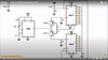
In the circuit you posted IC 1 counts from 1 to 10 (signals A to J). These signals are connected to 3 banks of LEDs (left middle right). But not all LEDs are on at the same time. This is where IC 3 and the 3 NPN transistors (2N3904) and multiplexing come into play. IC3 counts from 1 to 3 (pins 3, 2 and 4), the restarts from 1. When an output of IC3 is active (high), the transistor connected to this output will be on and only an LED in this bank (or group) can be lit. As IC3 is incremented each time the counter in IC2 overflows (goes from 10 to 1), IC3 will switch to the next bank at this moment.
An example:
IC2 is at 10 (signal J is high), IC3 is at 1 (pin 3 is high). Then the bottom LED in the leftmost bank will be lit since it is connected to both signal J and the leftmost NPB transistor which is on due to IC3 pin 3 being high. The other LEDs connected to signal J will be off because the middle and rightmost transistor are off.
With the next clock IC2 switches from 10 to 1, activating signal A (signal J is off). This transistion will in turn switch IC3 from 1 to 2, pin 2 becoming active, pin 3 becoming inactive. Now the top LED in the middle bank will be lit, but not the LEDs in the left or right bank, because only the middle NPN transistor connected to IC3 pin 2 will be on.

The big advantage of multiplexing is that you require much less wiring. As you can see you need 13 wires to drive 30 LEDs. If there were no multiplexing, you'd need 31 wires for 30 LEDs (30 for the anodes plus 1 for the common cathode).
Read more about multiplexing LEDs e.g. here.
 
I'm thinking that this is what I need. Can I run a second and third lead from each pinout on IC 2 and IC3 for the second and third circuits?

20-led-sequencer-chaser-using-555-4017.gif

Moderators note : shown image full size.
 
Last edited by a moderator:

Harald Kapp

Moderator
Moderator
I'm thinking that this is what I need.
Is it?
This is not a 20 LED chaser with 20 single LEDs lighting up one after the other. At every instant 2 LEDs will be on:
1+2
2+3
3+4
4+5
5+6
...
If you are lucky, that is. The 4017 are not properly reset durcing power on (reset pin 15 is tied to ground). Therefore the initial state of the 4017 is hopefully a count of 0 (pin 3 active), but this s not guaranted. The 4017 may also pwer up in any other state, e.g. IC2 might power up with a count of 1 and IC3 might power up with a count of 5. The sequence of LEDs will then be:
1+5
2+6
3+7
...
If the first sequence (1+2, 2+3, ...) is what you want, you will have to add a reset circuit to pins 15 of both IC2 and IC3. You can use a simple RC circuit as shown e.g. here.
Without the reset circuit the original circuit will work in any number of cases but fail in the rest of cases. This can be frustrating. Trust me, I have made that experience ;).
 
I see, still seems like it’s over engineered when placement of the LEDs and or only one CD4017 could achieve the same results.
But I guess it has its uses.

Martin
 
I see, still seems like it’s over engineered when placement of the LEDs and or only one CD4017 could achieve the same results.
But I guess it has its uses.

Martin
What do you mean placement on the LEDs on one CD4017? I'd like to keep this as simple as possible. Thanks.
 

Harald Kapp

Moderator
Moderator
Looks suitable. The overflow (pin 11) from the top 4017 routes the clock from the 555 to the lower 4017 once the top 10 LEDs have been lit. Then back to the upper 4017 once 2nd set of LEDs has been lit.
 
Top