Maker Pro
Maker Pro

My Power Supply Black Outs

I'm developing a control system for an electrovalve with a microcontroller. The electrovalve functions with 24VAC and consumes between 1.5 and 1 Ampere. My initial testing configuration used a 5V Cellphone charger to supply the microcontroller, a transistor and a relay; while the electrovalve was conected with the relay to a 24V-2A Transformer. This worked perfectly, so I moved on to the design of my power supply (to avoid using the charger, as I want to use only one power supply for the whole thing); this is where things get nasty:

-The power supply seems to work fine without anything connected, however, when it is supplying the circuit and the electrovalve is activated a brown out occurs and the microcontroller is reset.
-I am using a 7805 as regulator and it heats after sometime,
-I do know there is a design flaw in the power supply, but I don't know where exactly. I have searched the Internet for 5V power supplies and most people do them the way I do.
-I am also sure that the problem does not come from the transfomer (e.g. the circuit needing more current) as if I connect another 24V transformer just for the electrovalve, the brown out still occurs.

Here's my circuit:
4kifb7.png


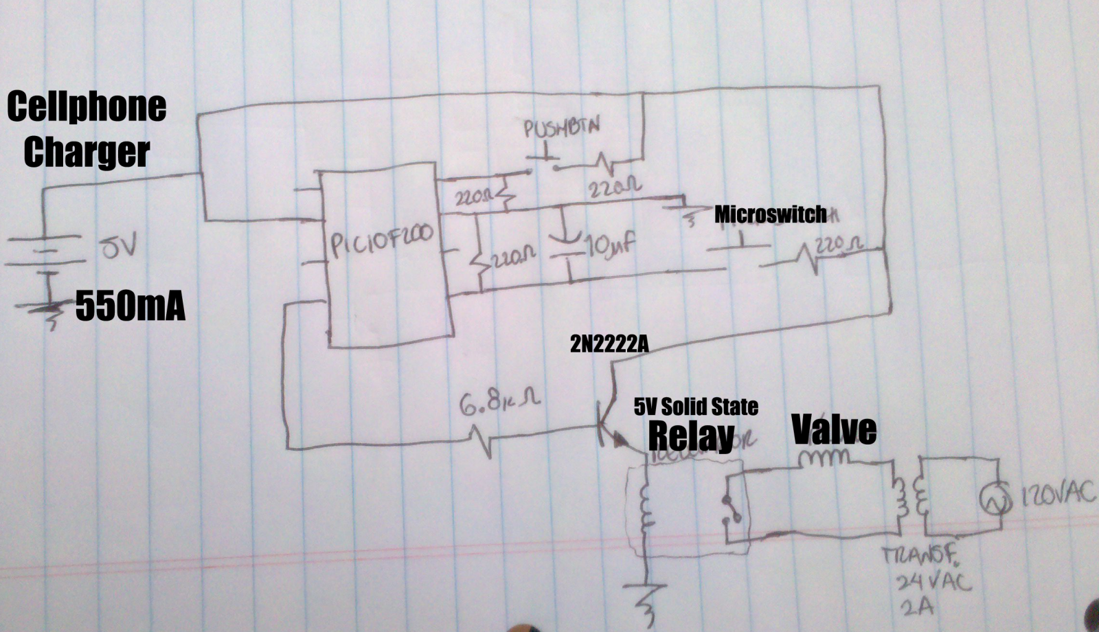
The design of the power supply is as follows:
24VAC Transformer ---> Rectifier Diode Bridge --> Filtering with 4700uF ---> 7805
Those are all of the components.

Hope anyone can help, thank you!
 

(*steve*)

¡sǝpodᴉʇuɐ ǝɥʇ ɹɐǝɥd
Moderator
The first thing is that the 24V transformer is probably generating a DC voltage around 36 volts. The 5 volt regulator reduces this to 5V.

However, this means that the regulator has to dissipate a little more than 5 watts for each watt consumed by the circuit.

It is possible that the relay consumes sufficient current that the regulator overheats and shuts down.

Attaching a heatsink, or using a lower voltage transformer (say, between 6VAC and 12VAC) will probably help.

There is also the possibility that you have something else wired up wrong.

Thanks for your reply Steve. Indeed, I also think the regulator is dissipating a lot of power; should I try with another regulator (other than 7805) or just another type of packaging?

About the wiring, I am sure nothing is wrong as I have rewired several times and checked thousands of times.

Oh! And I cannot change the Transformer as the electrovalve requires 24V to function. But I am using the central tap for the control power supply; so the voltage is about 18V.
 
Last edited:

(*steve*)

¡sǝpodᴉʇuɐ ǝɥʇ ɹɐǝɥd
Moderator
OK, *how* are you using the centre tap? are you using 2 bridge rectifiers, or a single bridge rectifier and the centre tap of the transformer as a "middle" supply rail? (the latter is correct)

What package is the regulator in (TO-220, or TO-92 are the likely possibilities)? Another type of 5V regulator is unlikely to help, use a TO-220 package and add a small heatsink.
 

(*steve*)

¡sǝpodᴉʇuɐ ǝɥʇ ɹɐǝɥd
Moderator
OK, that's fair enough. I presume that whatever else is using the 24VAC is completely isolated from this circuit?
 

(*steve*)

¡sǝpodᴉʇuɐ ǝɥʇ ɹɐǝɥd
Moderator
No, that's fine.

Have you connected the valve directly to the transformer? What current does it draw? Does the voltage across the transformer fall?

When the whole circuit is in place, does the relay pull in then release? or does it "chatter"
 
Yep, I draws between 1 and 1.5 Amperes. But no more than that. And no, the voltage does not fall.

About the relay: The microcontroller keeps it alive for about 1 second and then turns it off. But, sometimes it does kind of chatter, I mean, it suddenly turns off or don't even turn on, other times turn on and off very rapidly (not so common).

I know for sure the microcontroller is doing his work as it works fine with the cellphone charger.
 

(*steve*)

¡sǝpodᴉʇuɐ ǝɥʇ ɹɐǝɥd
Moderator
Have you measured the voltage on the 470uF capacitor while the circuit is misbehaving?

If not, do it now. See if it dips at all.

Also measure the output voltage of the regulator. Any dips below 5V are bad.

I notice you don't have a capacitor on the output of the regulator. Perhaps 10uF here would be good.
 
I will do that. Thing is, its past midnight in my country and I do not have an oscilloscope with me to track the dips. I will also add the missing capacitor. I will let you know what happens next! Thank you! I shall sleep now and work tomorrow morning.
 
Ok, so I added the capacitor in the regulator output. However I haven't measured the dips with an oscilloscope, but I did with a multimeter. There are some voltage drops (like about 1 V) whenever the valve is activated; does this mean it is drawing to much power?
Maybe that's the cause of the brown out. Do I need another kind of power supply? Perhaps a switching one? Or even another type of transformer?
 
A 1V drop would not be unexpected and would not affect the output of the regulator.

Is the relay really a solid-state relay as shown in your original schematic or is it an electromechanical relay? If the latter, you should have a reverse biased diode across the coil to supress the voltage spike when the relay is turned off.

Bob
 

(*steve*)

¡sǝpodᴉʇuɐ ǝɥʇ ɹɐǝɥd
Moderator
The 1V drop on the output of the regulator means one of:

1) your load is drawing more current than the regulator can suply
2) the regulator has gone into overtemp shutdown (or is going...)
3) the input voltage has dropped significantly (needs to be at least 7V)

If the regulator is not hot to the touch you can eliminate (2), to eliminate the others you need to measure the current drawn by the load and/or the input voltage.
 
Ok, sorry for not responding faster but I think the problem has been solved. I measured the current and it was no higher than 0.1A in standby, however, it raised to 0.5A whenever the valve activated. I also noticed than in these occurrences it heated a lot, so I added a heat sink to the 7805.
Along with the 10uF capacitor I addded to the output of the 7805, it seems to work now.
I also soldered the circuit to a phenolic board, I do not know if it was a major factor in why it was not working on the breadboard.

Thanks everyone for your help! I have some minor fixes to do, but it seems to work at least.
 
Top