Maker Pro
Maker Pro

Motomaster battery charger has failed

Hello. My dad's battery charger has failed. It is a Motomaster 141-243-904 from 1994. He says he was charging a car, and when he came back one of the clip was on the ground. When he attached it back to the pole the charger smoked and stopped working.

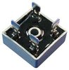
The rectifier is a big plate with 4 diodes. The ones on the left appear to be working while the ones on the right are shorted. The right side is also the one that is damaged as you'll see in the picture I'll post. The transformer is very rusty and noisy but appears to be working. So I think all this charger would need to work again is 2 new diodes. Unfortunately they really do not want you to change the diodes, everything is riveted and weld together, you can't even remove the diodes without brutalizing the rectifier. And I have never seen this type of diode before, they are short black circles.

What is this type of diode called?
What are the ratings/specifications to take into consideration when choosing a replacement?
How come only the negative lead goes through the rectifier?
What would you replace the diodes or whole rectifier with?

https://i.ibb.co/NnpK7Y5/DSC07422-min.jpg rectifier
https://i.ibb.co/wRC7QLQ/DSC07423-min.jpg diodes
https://i.ibb.co/PF0swNn/DSC07426-min.jpg charger
 
Can you look on the charger and get a photo of the specifications of the charger, primarily the output charge current ability.

As you say, the transformer is likely to be ok as they are fairly robust pieces of gear.

Just a note for future....always disconnect from the power when placing or removing charge clamps and always check polarity.
Good idea to replace the crappy clamps that started all this in the first place as well.

It is possible to replace the diodes with stud type but this might be beyond your ability.

If the unit has an output below a certain level, the rectifier unit can be replaced with a solid state one piece unit such as shown in the link below.

https://au.element14.com/solid-stat...=KNC-GAU-GEN-SHOPPING-SEMICONDUCTOR-DISCRETES

In these, the transformer out go to the ac terminals ( diagonally opposite each other) and the output goes to the positive and negative leads as marked, again on diagonally opposite terminals.
A small amount of modification is required to terminate on the rectifier from your existing wiring but a few spade terminals and some short lengths of flex cable (2.5sq. mm) and connectors and a screw and nut to mount the bridge unit would cover it.
 

Attachments

  • 4616675.jpg
    4616675.jpg
    8.1 KB · Views: 4
Last edited:
Ah...one of those monkeys.
Are you certain it is faulty diode and not the selector switch..??
I have a feeling you are not telling the whole story like "hooked up backwards" by any chance..??

Anyhow to answer your question...
You will need a very hefty (100A or more) rectifier bridge using stud diodes as I originally stated.(or the clamped units as are there now)
The latter might be difficult to find though.
Just what size would need to be determined possibly from the part numbers on the old diodes.
A second look at the diode plate is a bit perplexing.
Normally one would expect to see a centre tap on the secondary with the diode plate you have there but I cannot see any.
Where was the negative output lead connected...??

In the Fig.1 below is how I think your setup is connected.

The bridge setup is shown in Fig.2 but looking at your diode plate arrangement I doubt it is done this way.

There is also a half wave rectified system but I cannot see this as possible with the original plate arrangement either.


Charger.jpg


I do not think they make bridge units of the type i linked to in such a high current rating.

5 seconds on ..... 115 seconds off is a duty cycle time you must adhere to when using the charger on a flat battery and start the engine.
5 seconds cranking....then leave the starter off for (at least) 115 seconds.
This allows all the necessary parts to cool off sufficiently before the next barrage.
 
I tested the transformer using the switches so no they should be fine.
I tested the diodes with my multimeter's diode mode. I don't really know how it works, but the diodes on the left show a reading in only one direction, while the ones on the right make the meter beep and show a zero in both directions, which means they are shorted.
I wasn't there when it smoked. What I wrote is what dad told me. He was charging a car, when he came back one of the leads was on the ground. When he put it back on the pole the charger smoked and stopped working.

Figure 1 is correct, only reverse the polarity. Only the negative lead goes through the rectifier, which I don't understand but apparently that's how chargers work? The positive lead comes out of the transformer, "centre tap" I believe it is called.

Also I wanted to know what this type of diode was called. I don't know if it's an "official" name but they tend to go by the name "button diode".
 
Figure 1 is correct, only reverse the polarity. Only the negative lead goes through the rectifier, which I don't understand but apparently that's how chargers work? The positive lead comes out of the transformer, "centre tap" I believe it is called.

Button diodes would be the correct name i believe.

As for the Fig.1, as they say in Thailand , same same.....diodes are different polarity, principle the same.
The part number from the diode would be a good start when looking for replacement.
When replacing the diodes, do the whole 4, not just the 2 dead ones.
I would imagine the rating ( as there are 2 in parallel) would be at least ( given the 100A nameplate rating) 60A.

Voltage rating would I imagine be over 100V.
Not so much for rating as a lower , perhaps 50V would suffice, but for availability,100V would possibly be more common.

Stud diodes I believe would be more available type.
Given they are ( refer below) Case Anode type, you could replace all with stud diodes which would require drilling the heatsink plate.
As the studs would now protrude behind the plate, the plate would need to be put on spacers to clear the internal rear cabinet.

Redrawn Fig.1 for Case Anode rather than the case Cathode previously......

ChargerFig1A.jpg

Note that your button diodes, because of the button structure, may well be known as Case Cathode.
A simple check of the remaining good diodes would conform this.
Get the numbers first though.

Curious where the "smoke" came from though.
No indications of anything burnt...??
 
Last edited:
Bluejets said:
Curious where the "smoke" came from though.
No indications of anything burnt...??

Look at the upper-right diode, the insulation of the wire was starting to burn and the plastic melted. Then look at the lower-right corner. The insulation of the wire completely burned and the wire cut. Unfortunately my picture is misleading, it looks like only the insulation burned but no the wire itself cut too. This is what broke the circuit.

I'll come back with more info later.
 
Looks like localised bad connections given parts of this same circuit are in series.
Usually these show up under load /extra load conditions.
 
Top