Hey there
I'm trying to mod an atx supply with the at2005 chip.
I've put a 50k pot between 12v rail and ground with the wiper going to pin 2 (voltage adjust)
Problem is that as soon as it hits about 13 volts it shuts down due to I suspect over voltage protection circuitry.
Is there a way of disabling this?
Your help would be appreciated, thanks in advance -
knifey


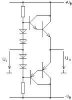
 Is that right?