Dear all,
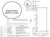
I have a microcontroller which I want to connect to a stepper motor and make it turn. I have output pins going from the microcontroller via a breadbord to the stepper motor.
The Stepper motor I have is:
http://www.robot-italy.com/en/42byghm810-nema-17-bipolar-48mm-stepper.html
I read a lot about the motors, but are still a little unsure how they are controlled. My questions is: do I need a driver or can I control the stepper motor directly. As far as I understand it, I only need to send a current to the correct stepper motor input pin, and it should turn?
Thanks!
")