Sir Zdenek668 . . . . .
QUESTION . . . . . . is there any sign of power presence on any part of the chair, by any activity or LED indicators or display ?
ANSWER ?
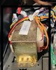
Viewing the transformer we can expect the two paired sets of windings ORANGE leads as being your two 24VAC secondary windings.
You will have to fill us in on the left side of the transformers wiring as I see a definite RED and BLACK as potentially being a primary wiring set.
BUT . . .are the bundled pair of larger YELLOW wires just passing by, and not actually entering into the transformer ?
But if they are, they might be related to a second primary winding that would be associated for optionally wiring this chair to run on 220VAC . . . however the two support boards are ticked off as being for 120VAC operation.
Without a wait for your response that that aspect, in the interim get your meter in hand and set to OHMS function mode . . .not in its diode / continuity test . . .set to its lowest range
IF its not being a smart / auto ranging unit.
Observe the display for what an open circuit is showing on your meter, then short the test leads together to see what a " short " reads as . . .and expecting your test lead loops resistance.
Then track down the RED & BLACK wires connector and see if you have resistance or an open circuit.
If the YELLOW wires were transformer connected, check out their associated connectors resistance.
A CONTINUANCE . . . . . . I had to leave for other more pressing tasks in the interim . . . .
BUT, I now see that " the shredder " has since come back with his "plug 'er in" and check its output voltages request.
We both, now are awaiting that info.
I also now have a better revealing photo that DOES confirm the extra wires coming into the primary side of that transformer.
https://www.electro-tech-online.com/attachments/f1a98796-dfa8-4e3a-81d5-2f31a585693f-jpeg.132996/
Therefore I tend to want to visualize a series aiding combination of the two primary windings for 220VAC operation, or a properly phased paralleling of the pair of windings, for 120 VAC operation.
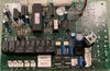
OBSERVING YOUR POWER CONTROLLER BOARD . . . .of post # 43
For sure this baby boards father must have been a TREADMILL CONTROLLER. . . .due to their similarities .
Split this board down the center and the left half will be constituting a power controller.
AC power comes in at JK1 2 pin connector , then there is its rectification with the big BLACK FWB block and then its rectified DC storage at the two large black E-caps to the left.
What are their capacitances and voltage ratings ? Then that DC power passes down to an un viewable POWER FET ? that the gold sheet metal screw on the center of the heat sink is mounting . . . but, its other sides companion HEAVY D1 damping diode, you are able to see.
Then there is an on /off power switching relay with its unwanted " inspector A's " green label, which we don't need! , since its blocking the relays part number, but since the rest of the unit is using 12V coil relays, we assume the same coil voltage for this relay.
Finally, we can see the output from the POWER FET's controlled output routing over to the JK4 2 pin connector that feeds the most powerful motor / or / mechanatronics associated with this chair. Finally there is that 0.08 ohm 7 watt resistor that is suspicioned to be inserted from that J4's second pin to ground . . .
or . . .its being the POWER FET's source resistor to ground. Either will give a small comparison feedback voltage to reflect the degree of mechanical loading being subjected to . . . . . in order to then engage corrective feedback.
Wh a a a a a at ? . . . . .
Is there being the circus's 500 lb fat lady plopped (and that's being heave e e e e on the PLOPPED, down in that chair . . .or is it a 5 year old . . . . see the variances in loading ?
The final few things . . . .
The relay driver is Q4 and has its damping diode beside the relay
The JK5 connector and its need of isolation by the 4 O.I.'s just above it, fed by this boards custom 18 pin u/P, just above them.
Further up the board at the left as a smaller 2A 600 V round black FWB for a minor sub/ supply from its AC voltage source coming in from JK2 connector.
Its main DC storage capacitor would be the big blue E-cap above it . . . . .
give us its capacitance and voltage rating.
Just to the right there is an 8 pin DIP I.C. . . .suspicioned as a dual op amp or comparator, which spits its output to the JK3 connector at top.
Can you give us its part marking, to confirm ?
The only two final items, that are fuzzy in my mind, are down at the very bottom of the relay.
Looks like two POWER plastic cased transistors ? / FET's ? mounted side by side.
Can you confirm their part numbers . . . . and they might be different . . .as in complementary pnp/npn or p /n pairs.
I am now dependent on the firstly mentioned two large black caps, in order to ascertain JK1's AC supply voltage.
If being 24VAC this certainly will be ONE of your POWERFUL 24VAC supplies, but not the 2W05's minor supply, unless it is piggy backing on one of the 24 volt windings.
OBSERVING YOUR MAIN BOARD . . . .of post # 47
This time the divisional line is across the center of the board with the POWER portion on the bottom
If our earlier studied board rated using one of your power transformers 24VAC windings, this one certainly rates using the other one.
I'm suspicioning 24VAC input from the 2 pin connector just viewable below the heat sinked FWB black block . .
.OR . . .the two pin connector
with a frontal marking of V1 visible .
MYSTERY . . .? . . . why the second FWB twin unit at the 8:00clock position from it . . . .but with it . . . . not ALSO equally rating its own heat sink ?
Then the sole, largest BLUE E-cap must be one of their storage caps . . . .why is there not a duplicate second one, for the other FWB block ?
What are the blue E-caps voltage and capacitance values, with the minor cap hardly being significant for its minor storage capacity.
Just to the left, I am seeing a full blown H controller with dual opti coupler feed at the top and the TR1-TR2 POWER transistors.
This should be for the second strongest demanded motor / or / mechanatronics being utilized with this chair.
I suspicion the MOTO 2 pin connector as this controller units output 2 pin connector, with it also using 1 of the LARGE power relays .
I suspicion a second LARGE power relay used with the CX function and being outputted into the CX . . . . . 2 pin connector.
I suspicion two power relays and the two center silicone blobbed TO-220 POWER devices along with the IC to their right side as being anither motor / or/ mechanatronics controller and outputting into the F_U_D and L_D_R? pair of 2 pin connectors.
How about their part #'s ?
Finally, the set of two smaller relays at the end and and their controlling the up and down recline of the chair and their feed out into the sole 2 pin end connector.( They just reverse power polarity to the motor and stop on demand . . .at that specific position. )
HEY . . . now its time for you to tell us what are the two connectors on these modules that the two ORANGE 24VAC supplies, connect into.
Also I'm now going back and BOLD RED highlighting each first word of an informational request.
NOTICED . . . .
Of no particular evidence of severe overheating of that transformer, with your nose right up to the top paper over wraps, is there any residual burnt smell ?
Your readings will determine the next steps.
73's de Edd . . . . .
I always carry a spare pair of pants when I go golfing . . . . . just in case I get a hole in one.
(Think that over vewy-vewy cawefully. . .for the other potential NEED of that second pair of pants) . . . . . . . .
.
.