Maker Pro
Maker Pro

Making new AC DC transformer for La Z Boy chair

Hi there. Hope this is the proper place to post this. I have a La Z Boy recline/massage/heat chair. The power supply is missing. The original power supply had a 3 pin connector. 27 V.D.C 1.2a and 24 V.A.C 1.5a.

I am guessing the three pins are 27Vdc, 24Vac, common ground.

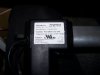
I have a big transformer from a big stereo system that has a whole bunch of AC out puts, 14v, 36v, 12v, and 24v.

I'm thinking I could probably ... Now I get it. I don't need all that. Did some thinking here as I was typing. They would have used one 24V AC transformer for both. Just add some caps and diodes to create the 27VDC.

I guess I don't need this big old brick. I could probably make something much smaller if I could find a 24VAC transformer.

Could anybody lead me in the right direction here? What is the minimal supply list I need to build my own transformer so I don't have to buy it for $99.99 on ebay?

Jonathan
 
I guess in the interest of learning, I should look up some indestructible on how to make DC power supplies and do some searching. I'll go ahead and do that. Sometimes I just think better out loud. Feel free in the mean time to point me to some good reading material on this subject. :)
 
If by "build my own transformer" you mean getting some grain-oriented steel stampings, a bobbin or two, and a pound of magnet wire (two different sizes) and winding a transformer from scratch - I strongly recommend that you don't. Even if you got it to work (a very big if), there is no way it would be as safe as a commercial product. You need a simple control transformer, (whatever your power line voltage is) in and 24 Vac out at 3 amps. After that, a bridge, cap, and LM317 will make the 27 Vdc. Tons of innergoogle schematics for that. Or buy a switcher regulator module on ebay for $3. Either way, ***buy*** the transformer.

ak


Yup. I didn't word that right I guess. By build I meant take a 24 Vac transformer and make it DC with a few added components.

I'm also beginning to second guess my common ground theory. Is that even possible? I'll have to check to see if there is not another conductor in the outside ring of the plug. There's got to be a better word for that.
 
I'm also beginning to second guess my common ground theory. Is that even possible? I'll have to check to see if there is not another conductor in the outside ring of the plug. There's got to be a better word for that.
Yes, that would not be possible without 2 transformers (or 2 windings on one transformer).

Edit: Replied too quickly. You could have a common ground if a half-wave rectifier is used for the DC, but not with a bridge, which is better and more common.

Bob
 
I found a transformer the puts out 22.79Vac in my junk drawer. It has letters and numbers on it, but nothing that makes sense to google. Would this be an appropriate transformer to use or do I need to figure out how many AMPs it is able to produce?
 
do I need to figure out how many AMPs it is able to produce?
Yes, if you don't want to fry the transformer. If it's difficult to source a 24V 3A tranny you might find it easier/cheaper to use a 24VAC 1.5A (preferably 2A) one, plus an off-the-shelf 24V DC 1.2A (preferably 2A) power supply.
 
I found a transformer the puts out 22.79Vac in my junk drawer. It has letters and numbers on it, but nothing that makes sense to google. Would this be an appropriate transformer to use or do I need to figure out how many AMPs it is able to produce?
You can use size to estimate the power of a transformer. Look up some 24V 3A transformers. If yours is similar in size / weight, it might be capable. If it is significantly smaller, no way.

Bob
 
Ok based on BobK's
You can use size to estimate the power of a transformer. Look up some 24V 3A transformers. If yours is similar in size / weight, it might be capable. If it is significantly smaller, no way.

Bob


Ok based on this I decided to go ahead and try with this one. It is quite big and completely encased in brass coloured metal. Here is the board I made for it. I get 23Vac and 34.4Vdc. Hope that makes sense since it was asking for 27Vdc. Should work I think. A little sloppy on the soldering, There are a few extra spots of soldering because I started out with a 35v 3300u cap. Then just before I powered it up. I checked over everything and decided that thing was too small so I pulled a 50V 3300uF from a board I had sitting here. If that isn't big enough I cannot help it. :)
 

Attachments

  • 102_0504.JPG
    102_0504.JPG
    241.9 KB · Views: 71
  • 102_0503.JPG
    102_0503.JPG
    207 KB · Views: 79
Does the capacitor have a domed end? if so it is likely to be faulty. The 34.4V will drop under load so the 35V capacitor should do.
 
Something's not right. The AC stuff (vibrate, heat) works well. The actuator does not work. In fact when I plug the actuator in, the lights on the remote dim and nothing works anymore. Could be the cap I guess. Will have to check. The top of the cap is flat. Looks ok.
 
I'm having problems with this circuit. Can anybody advise me. The actuator is 24Vdc. The DC output of the board I made is closer to 30Vdc. The actuator does not work at all. Is there an over voltage problem or is there something else I should be looking for?

Jonathan
 
Have you got the right polarity on the capacitors?
Is there a flywheel diode across the solenoid which would conduct if the polarity is wrong?
 
The polarity of the capacitors is right. I have never heard of a flywheel diode. That's understandable, I have come across a lot of stuff I have never heard of in the last week or so. I will see what I can find. Questions like this are helpful. They give me stuff to think about.
 
When an inductance like a relay coil, solenoid coil or DC motor is turned off, the energy due to the magnetism has to be dissipated in some way. Normally, a spark would be formed at the switch, this may burn out contact points or fuse semiconductors.
A diode placed across the inductance will allow current to flow until the energy is dissipated as heat in the windings. This diode must be fitted in such a way that it does not conduct when the solenoid is operating but does conduct for a short time at switch off. It is therefore important to connect it the right way round. Some devices have the diode built in so the device must be connected the right way round or it will provide a short to the supply.
 
I guess there might have been such a diode in the original power supply, Sounds like it should be easy to add to my board. Now the question I have is this. Shouldn't it work at least without the diode in place? If there is no movement in the actuator at all there is no current to flow. It could be that my semiconductors (transistors) are already shot from the first time I tried to use it.
 
If the lights dim when the actuator is plugged in then current is being drawn, you just have to find out where.
A lack of a flywheel diode will give very high voltage on the collector of the switch when it is switched off and could pop the transistor.:(

You could try with a resistor instead of the solenoid. This should not damage the transistor and will determine if the circuit is working. Then you could try the resistor in series with the solenoid to limit the current. If this seems to activate the solenoid a little then the resistor could be removed.
 
It is not a Solenoid. It is a Deltadrive actuator. It also says Connection on to class II DC circuit. What makes a circuit class II?
 

Attachments

  • 102_0505.JPG
    102_0505.JPG
    181.8 KB · Views: 67
It is not a Solenoid. It is a Deltadrive actuator. It also says Connection on to class II DC circuit. What makes a circuit class II?
Sorry, my mind was on another thread.

Ah, so it is a DC electric motor with the polarity reversed to reverse the actuator direction.
It looks as if it takes 2.2A. Have you measured this at the recommended 24V DC.

If you get no action with a couple of amps, then I would suspect mechanical problems. The specification is for intermittent use thus a sticky actuator will over stress the system.
 
Top