Sir Stoneww . . . . .
And so . . .I checked EVERYwhere, to confirm that this was NOT being ALL FOOLS DAY / APRIL FOOLS DAY, and a quick query of Professor
Ulysses
P. Fips had confirmed that he had not tried to pull a fast one over on on us.
So I just ventured into what was being presented here, for its analysis.
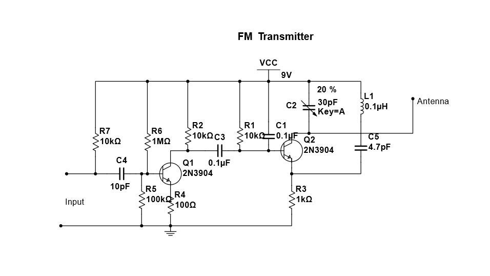
Starting at the initial audio amplifier circuitry of Q1 and its initial audio input, one would expect that R7 top lead to be swung down and connected to the common ground buss.
Then one needs to pull out calculator and impedance chart and spread sheets to determine the auidio output level and frequency range expected to be passed thru C4, at a 10 pf value. Then you look further down the circuitry and see the 0.1 ufd that will be delivering the resultant amplified audio to the base of Q2.
It will respond to that varying audio and in turn, Q2 will squegg its operating frequencty proportionatively to create the required FM frequency shift aspect of FM modulation.
Looking at the C1 path right up directly to the battery and with the battery providing an almost zero attenuated path to ground, . we'll certainly not be seeing any RF on the base of that Q2.
So we must be having ourselves a grounded base oscillator circuit. But in looking at the collector and emitter of Q2 , then one then needs to confirm . . . . . is the collector getting its DC operating power from C2 or the antenna wire Hmmmmmmmm . . . .HMMMMMMMMM ?
You SIR . . . are guilty . . . . . .guilty as sin . . . . . .
GUILTY AS CHARGED . . . . . of passing a
bogus schematic .
Soooooooooo you go back and "GOGGLE"
sic. . . . . . "GOGGLE"
sic HARD, REAL HARD . . . until you find
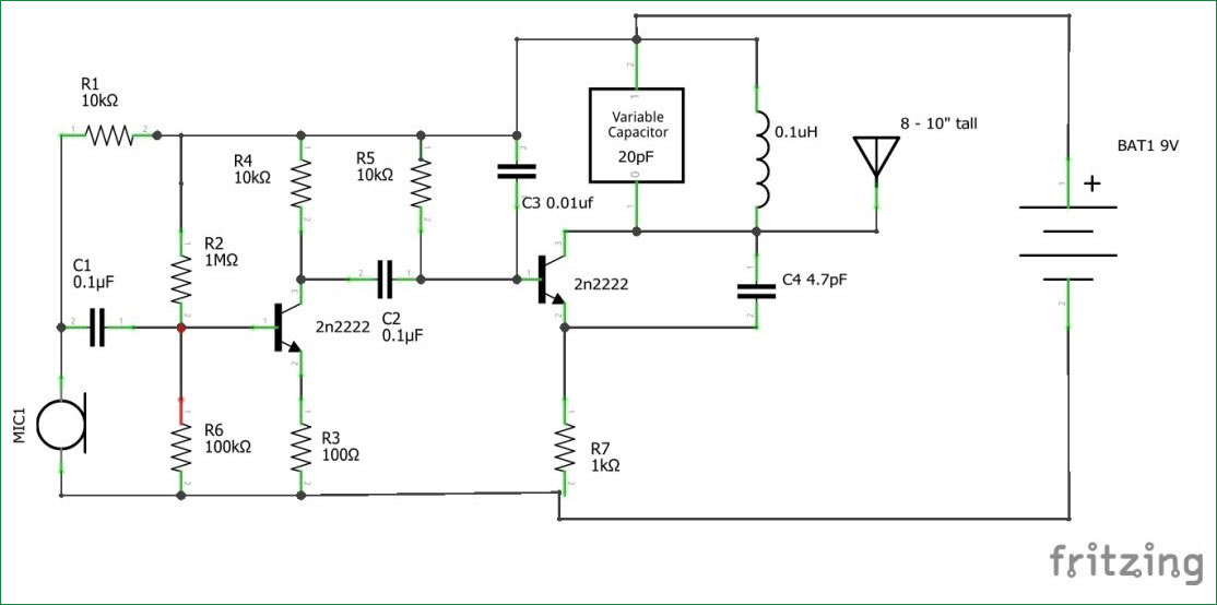
https://circuitdigest.com/electronic-circuits/how-to-build-fm-transmitter-circuit
Then, it is being readily apparent that the reason for the R7 situation /wiring, was to supply operating power for the fet amp being used within an electret design of microphone cartridge.
C1 will
now pass the audio spectrum with proper use of a .1 ufd value.
The connector
DOT on the schematic at the junction of the resonating inductor and C4 , changes a potential series resonant circuit to a tried and true parallel resonant circuit using "Variable capacitor" / 20 pf and companion .1 uh inductor, with C4 serving as feedback coupler to even initially permit oscillator start up.
READ it all and he tells you all.
Plus . . .at no extra charge , you
now have DC operating power getting to the oscillators collector.
AND iffen you can't ever get this critter to work for you . . . . maybe Uncle Scrooge, here, will come on and give you his purportedly tried and true FM xmitter circuit.
Thaaaaaaaaasssssit . . . . .
73's de Edd . . . . . .
Everyone hits a brick wall now and then; but, as you soon learn . . . . the REAL trick is NOT to do it with your head.