Maker Pro
Maker Pro

Magnet Alarm Circuit Board, Battery Power

Status
Not open for further replies.

davenn

Moderator
Does the piezo make pulsing sound because circuit is RC oscillator?

As I said earlier due to lack of info, unknown ... but as a general case, a plain piezo like that requires an external osc


so why is a magnet motion detector an oscillator circuit?

that is just the door etc open/close detector, nothing to do with the osc/piezo

D
 
There's no crystal on circuit board, so oscillator must be RC, tuned to a frequency for piezo, but how does it make pulsing sound? I just unwrapped black cylinder that external magnet (door open/close detector) is attracted to, thinking there might be a crystal, but found copper wire coil. What does this do?
 

Attachments

  • coil.jpg
    coil.jpg
    248.9 KB · Views: 182

davenn

Moderator
That's an inductor ( well was till you destroyed it)
it's not going to work again, I can see a number of damaged wires in the coil
 
What does this inductor do as far as being connected to the iron cap that is attracted to the external magnet? How does the piezo make a pulsing sound?
 

davenn

Moderator
What does this inductor do as far as being connected to the iron cap that is attracted to the external magnet?

The inductor has a ferrite core, the magnet just happens to be attracted to that ferrite ... wow, there's a surprise ;)

How does the piezo make a pulsing sound?

I have already answered this 2 or 3 times ... when will you acknowledge my answers ?

WITHOUT KNOWING what that IC does, that question cannot be answered

Dave
 
I did some measurements to the circuit, and found out that the transistor grounds pin 5 when the magnet is close to the circuit, and pin 5 'floats' when the magnet is away (and the alarm sounds).
So the magnet closes the switch, which then grounds pin 5 via the transistor.

It would be more cost effective if the switch itself could ground pin5, but probably the switch resistance is too high to force pin 5 to ground, so the designer must have taken 4 extra components (the transistor, two resistors and a capacitor) to make sure that pin5 is grounded when the magnet is nearby.
Side effect is that the circuit draws a small extra current to keep the alarm off when the magnet is close to the circuit.

I did not measure, but assume that when the alarm sounds, pin 1 swings at the alarm sound frequency between supply voltage and ground, and this is then transformed by the small transformer(!) to higher voltage to drive the piezo. (note that the black cilinder actually is a transformer: primary coil pins are soldered to the circuit board, secondary to the red wires of the piezo)

Pin 4 is supply voltage, pin 8 ground. The functions of the other pins (2,3,6,7) is unknown to me.

Yash
 
I just spotted this thread. I have a number of almost identical door/window alarms. It should have worked perfectly well from external power.
I used one for a cheap miniature siren, with a transistor switching across the reed switch to operate it. They only cost a couple of dollars each.
I just dug them out. Actually, although I do have some almost identical to your's, they use a 'blob' IC rather than a through-hole type. (The transistor is mounted on the top of the board and can't be seen in my pic.)
And it was a different brand unit that I hacked in to, a 'Quell', but they're much the same internally.
I just connected an external 5V to the one that looks similar to your's and it works fine, p1ne.
You need to get the polarity right. The spring-like end of the battery terminals is positive with button cells, not negative as with other, larger batteries. (I know you said you tried it both ways, but try it again if you have another undamaged unit.)

100_6168_sml.JPG

And if you want to run a fan when a reed switch triggers, put that alarm aside and just use a reed switch, transistor and fan.
 
Last edited:
Is your window sensor part of a wireless alarm system, or is the piezo sounder the only alarm indication?
hevans, these are a cheap, stand-alone alarm. The piezo is the only output.

I bought a couple of equally cheap units from eBay a few weeks ago that transmitted at 433MHz, (no receivers included), but they transmitted a raw, uncoded burst, so I threw them away and made my own system using separate alarm system housed reed switches, a coded remote control encoder IC and small cheap 433MHz RF transmitter, transmitting to a matching 433MHz receiver with coded remote control IC. (I used a PT2262 / PT2272 12-bit tri-state pair for the encoding & decoding. 533,431 potential codes.) It works a treat.
 

hevans1944

Hop - AC8NS
@Old Steve you may not have noticed that I quit responding to this thread when it became obvious that @p1ne didn't have even the slightest clue about what was going on, even after @davenn and some others took the time to explain things. Some people here just like to tinker (nothing wrong with that!) and buy cheap stuff, open it up, and try to figure out what is going on inside. But if they haven't taken the time to learn the basics about electricity and components, it is very difficult or even impossible to answer their questions in a way that they can understand.

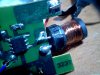
For example, the OP discovered that a magnet was attracted to the ferrite core transformer and from that jumped to the conclusion that this component was also a magnet, despite the fact that it has two terminals soldered to the circuit board and two terminals connected with wires to the piezo transducer. In his starting post he mentioned that there was a magnet inside the case, mistaking the ferrite transformer core as a magnet. He later discovered it wasn't a magnet by removing the shrink tubing around it, probably with a sharp hobby knife, and in the process cutting some strands of wire in the secondary winding, thereby bricking the device. No big deal. The OP said he was just trying to learn and the whole thing cost a buck.

@Colin Mitchell said the piezo transducer needed about 80 V from an oscillator to drive it, and said oscillator would not drive the 12 V DC brush-less motor fan the OP showed in an earlier photo. All true, but the OP did not make the connection between oscillator, 80 V, ferrite core transformer, and piezo transducer. The OP also appeared not to understand that the oscillator operates at a high frequency and is pulsed on and off at a much lower frequency to sound the piezo transducer, throwing out questions about RC oscillators with no clear understanding of what an RC oscillator is.

And there the tread rested until yesterday, when newly-joined to this forum @Sp1frlku0xCMKms0Yash posted his comment. So consider this thread hi-jacked.
 

davenn

Moderator
And there the tread rested until yesterday, when newly-joined to this forum @Sp1frlku0xCMKms0Yash posted his comment. So consider this thread hi-jacked.

I suspect @Sp1frlku0xCMKms0Yash is p1ne who had forgotten his login or something, just with the way the Q / comments were posed


anyway I doubt that the thread is going to go anywhere useful, so will close it
It can be restarted elsewhere if need be

Dave
 
Status
Not open for further replies.
Top