Maker Pro
Maker Pro

Looking for an electronic component - no idea what I need.

I am looking for a way to switch a circuit on with the same power source as the original circuit or a separate power source. The issue that I am having is I can not find a way to keep power to that second circuit using a relay once the original circuit switches back over.

my original project is here
https://www.electronicspoint.com/help-understanding-math-behind-schematic-t219655.html

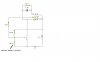
It's a very basic trip laser alarm. I want to expand this circuit so the alarm will sound continuously once the laser is tripped. I looked at a relay, but unless they make some sort of dual coil relay that I can switch using more or less V. I can't think of how this might be accomplished.

I will take any advice, even a link to a schematic that employs a technique like I need. Maybe a hint of a word so I can google it myself. Anything...
 

(*steve*)

¡sǝpodᴉʇuɐ ǝɥʇ ɹɐǝɥd
Moderator
there are multiple ways to do this.

Perhaps the easiest is to use a set of NO contacts on the relay to ensure that power remains applied to the relay after it is initially switched on.

An alternative is to use an SCR to turn on the relay. Once triggered, the SCR will remain turned on.

In both cases the relay would stay turned on until you remove the power.

There are many, many more ways you could achieve this.
 
Perhaps the easiest is to use a set of NO contacts on the relay to ensure that power remains applied to the relay after it is initially switched on

Not to be so naive, but how exactly are you wiring this,? Secondary power source? The SCR will work perfectly though and is a really good suggestion. Had I of only known about them before asking --shrugs


edit: NVM, after googling a little more I was able to see the error of my way. I needed to use a double post relay and use one 'SET' (just like you said) to provide positive feedback to the base of the transistor. I think that is what you meant, seems to work.
 
Last edited:

(*steve*)

¡sǝpodᴉʇuɐ ǝɥʇ ɹɐǝɥd
Moderator
no, if you're using a transistor to switch on the relay, placing the NO contacts across the transistor will cause the relay to latch on even if the transistor is turned off.

So same power source, just an alternate route to provide power to the relay coil.
 
Is this what you had in mind? is there anything significantly wrong with this schematic?

edit: dumb question removed. :)
 

Attachments

  • trip_laser_constant_alarm.png
    trip_laser_constant_alarm.png
    19.2 KB · Views: 136
Last edited:

(*steve*)

¡sǝpodᴉʇuɐ ǝɥʇ ɹɐǝɥd
Moderator
Perhaps you should try that one more time (this time with the schematic :D)
 
How does this look? The only thing I don't fully understand about this circuit is why I can't use a spst relay and hook the alarm/cap in parallel with the lead that comes off the NO contact of the relay that controls the base voltage after the relay has been tripped. When I put that in the simulation, the cap charges very slowly, But I don't see how it's any different. to me it still looks like it's in parallel the the 2.2k ohm resistor coming off the relay.

Also, how do I size the relay. What is most important when looking to purchase a relay used in this instance?
 

Attachments

  • relay_trip_laser_circuit.png
    relay_trip_laser_circuit.png
    17.4 KB · Views: 160
I do not see any reason why you can not use a SPDT relay or even a SPST-NO relay. As long as you are connecting the + side of the cap/alarm to the same place on the relay as the 2.2K but leaving the - side connected where it is now connected, things should work. If that is what you are doing and still seeing a problem, I would look at your relay model in the simulation software.

A small signal relay is really cheap. I would not consider buying it used unless new is simply not available.

You need a relay that has a 9V coil and a 9V or higher load rating with 200mA or higher current rating. Any mechanical relay you can find is likely going to be rated higher than 9V and higher than 200mA. Your problem is going to be finding one with a 9V coil. That is not a commonly used voltage. Any real distributor like DigiKey will carry it, but you may not have much luck at places like RadioShack.

Good luck.

---55p
 
Steve, is this what you meant? :D Took me a long time to see what you meant. I feel sort of embarrassed.
 

Attachments

  • relay_no_ground_latch.PNG
    relay_no_ground_latch.PNG
    17.1 KB · Views: 136
Oh, I wanted to ask another question about the base voltage once the transistor conducts and the relay latches. In my simulation it's telling me that I am getting about ~650mV to the base of the transistor (photocell = high resistance). This is down from the 750mV I used as the number to figure out my resistor values.

I am assuming that the relay and diode has some sort of internal resistance that I am not exactly aware of the values and since that would be in parallel??? with the two other resistors, it's affecting my overall resistance which changes my base voltage value.

#1. wouldn't I just need to take the voltage across the resistor and divide it by the current to get the resistance of the diode/coil? Then go ahead and figure out total resistance from there and work backwards? Little help here in this area would make things simpler.

#2. with the base voltage being ~650mV doesn't that mean the transistor would be in linear mode and isn't it this mode where the most power is consumed? I thought I read something about this recently. Not that this circuit would cause worry about leaving the transistor is linear mode, I am just curious...
 

(*steve*)

¡sǝpodᴉʇuɐ ǝɥʇ ɹɐǝɥd
Moderator
Last things first :)

The transistor will almost certainly go through the linear region between cut-off and saturation fairly slowly because your circuit has no hysteresis. This may or may not be a problem.

As long as the transistor eventually turns on enough to pull in the relay, the contacts across the transistor will ensure it gets very firmly pulled in, and will eliminate most of the power dissipated in the transistor (except for a small amount across the forward biased BE junction.

The answer to question #1 is essentially "No". Assuming the figures you worked out before are reasonable, the transistor will get turned on and presumably be abel to pass enough current to turn on the relay.

The difference between 650 and 750 mV is probably more due to a different model (or different values used in a model). In this case it's probably insignificant.

The most important thing is that with the photocell illuminated you get a far lower resistance than when it's not.
 
Top