Maker Pro
Maker Pro

Looking for a service manual / schematic

Found the 198 service manual but it refused to download on my PC for some reason, the capture did not load. I managed to grab it in the end on my tablet and email it to myself. It seems a lot more in that monitor than in the one I'm working on. The diode and resistor are in parallel on that, mine they are in series on the gate circuit for the MosFet.
 
It has been suggested that the 0805 resistor with the duff printing, might be 4R7, 4.7 Ohms, does that sound realistic? I have had a good look at VW198 schematic for the power board and that one is totally different configuration. The driver from the PWM chip is connected to the gate via a 10ohm 1/4w resistor in parallel with a diode. The VW195 is connected via a 47 ohm resistor in parallel the diode in series with a 4.7ohm resistor??
 
Last edited:
Update time, I have today ordered all the parts that I think I require, thats a new IC601, Q601, 47R and a 4R7 0805 resistors which will be arriving over the course of the next week. Already have the .22R fusible resistor, T2 fuse, so will be back on it then. In the meantime, I'd like to say many thanks to all the members who have given assistance so far on this project.
 
All parts fitted to the monitor, powered up, no bangs drawing .5W on standby but otherwise still dead, cut my losses on this and will be dumping it, after all it is already well over 10 years old so its not done bad and not worth spending another £20 on.
 
Sir specmaster . . . . . . . . . ( calib-wation techie ? )

RESPLENDENTLY COMPLEAT . . . . . . . ." UNITIZED " . . . ALL IN ONE . . .REFERENCING . . . . .
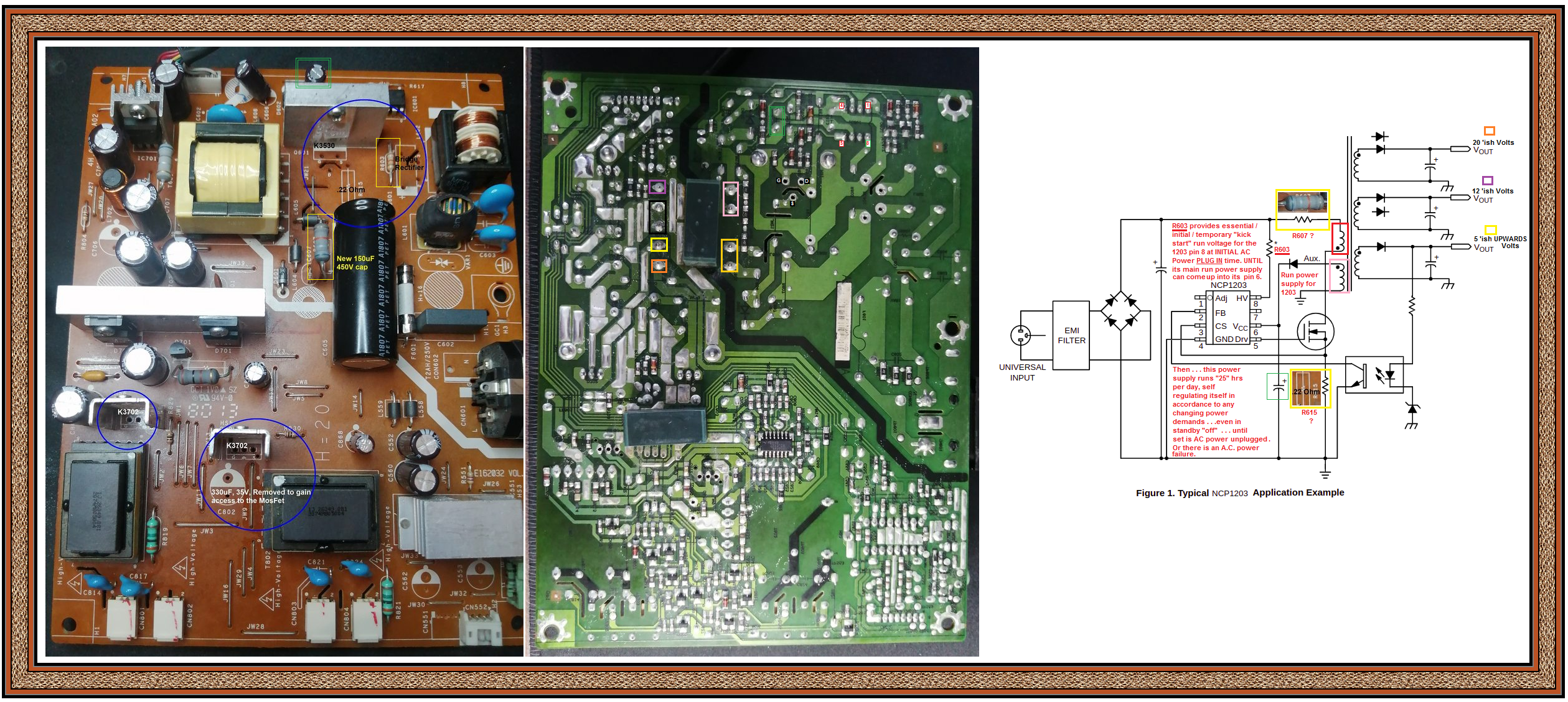
https://i.ibb.co/FwZ90gR/ASUS-VW195-Monitor-MARKUP.png


ASUS-VW195-Monitor-MARKUP.png


Lets consider that you leave the two K3702 power FET's out of circuit in the back light power supply section and just concentrate on getting the units
main power supply going.
Initially, ALSO leave Power FET K3530 off board. Then, seeing if you can observe the new NCP1203P60, to see if its initially putting out a start up pulse stream on its pin #5 at INITIAL . . . .AC POWER PLUG IN TIME.
REMEMBERING that this being an AC LINE HOT chassis and ground referencing is made to the minus of the 150 mike main filter that you replaced.


OBSERVATIONS . . . .


Are the critical parts I have marked / placed in with pics now good parts ?

Now, if you were initially testing by . . . . .

Instead of a 60W lamp inserted instead of the 2A fuse, how about fitting a new fuse and slowly bringing the power up via a variac?

Good procedure . . . . . on / for old tubed equipment . . . . . but on this unit, the fallacy is being . . . . . read my in RED comments on the right far side data sheet.

I would definitely still go for the lamp in place of the pigtail fuse, in progressing to further / later testing, with that NEW K3530 when eventually being installed in circuit .

Now power up the naked unit and see if only the 1203 pin # 5 will initially give out a short stream of start up pulses, UPON initial AC line power plug
insertion application.

With all of your displayed exotic meter collection . . . can I fully "consume" that you have a triggered scope and full intelligentia / expertise of using same?
IF NOT . . . I will 'jes hafta gives u a po' boy . . . .workaround.

HANG IN THERE ! . . . . . . . Don't give up !

Query me for more info / or / procedure . . . . . if in doubt anywhere . . . . .

Addended last thoughts . . .does that . . . white 11 ? pin corner output connector . . . . have any voltage markings on my UN-viewable side ?
And isn't that R603 being in the meggish range and tests good . . . with one lead out of circuit ?

IF YOU ARE ONLY READING THIS TEXT BELOW . . . REDUCE THE ABOVE MARKUPS SIZE.
What is the AC power . . .wattage consumption spec . . . . on the back of the monitor ?
Got a 1K at 3-5 watt resistor . . . or temporary cannibalizing source of , for ensuing testing .

73's de Edd . . . . .


Am I any good at delegating? . . . . . . . Damn sure ! . . . . . . I can always find someone else to blame!


.
 
Last edited:
OK, this evening I have had it back on the bench and before powering it back up again, I thought I'd go through and check to see if anything had blown when I powered it last time and nothing has blown and everything has so far checked out OK with the multimeter, diodes, resistors, fuse, fusible resistor, etc all seem to be OK, maybe tomorrow, time permitting I'll be able to get round to powering and testing the points you raised. I also checked the continuity from the soft power on button at the front back to the display board in case I had accidentally damaged the loom while disconnecting it etc, all is good there.
 
Update time, went back to basics again and measured voltages, at the locations you highlighted, zero volts but power is on the board and the bridge rectifier is producing DC voltage as expected 315V and no magic smoke was released. R607 reads as 67.1K in circuit, which is about right, R615 measures 0.22ohms (new one fitted), R603 is 17.6K. R613 and R617, I think, should be 1K but R613 looks slightly burnt and reads 5.7K, this makes sense as its the feed to the source of the Mosfet from pin 3 on the NCP1203, I have plenty of 1K resistors .25w which I can replace it with. One end of R617 is connected to pin 1 of NCP1203 (adj).

I also noticed that you had incorrectly identified the pins on the Mosfet, so I have relabelled them on the attached layouts.

Does this make sense to you? I won't replace R613 until I hear back from you, in case you think it will burn again if I don't check something else first?right layout1.jpg topside.jpg
 
Here is an application note from ON Semi further confirming the typical resistance values of the center burnt CS feed back resistor and the gate of the power FET's series resistor.
I'm suspicioning the burn out, due to backfeed from a fused together DGS junction of the power FET and a back feed of 300'ish of volts into the IC, thus wiping it out.
Now with those values . . . and no power FETS installed . . . do we scope that start up train of pulses at AC line power plug in ?

APP NOTE . . . . .
upload_2022-6-1_6-20-0.png
 
No, I have yet to scope the chip, I replaced the resistor with a 1K one and on powering up, no bangs etc, and I was getting volts from the transformer, of 7V, and 12V so something seemed to working, plugged the screen in and still no life (all the other Mosfets have all been placed back in circuit). Tomorrow time permitting, I'll scope the IC to see if the pulses are there. I guess because I was using a DMM with a very high input impedance, the voltages I was reading could be just ghost voltages that collapse when a load is applied?
 
Still not got around to it yet, the urgency has diminished as my son has a monitor at the moment, and I have a number of other things that I'm involved with at the moment, so I'm sort of ducking and diving from this to that sort of thing, and currently I'm trying my hand at video editing with DaVinci Resolve software and boy is that a steep learning curve for someone who has never been involved in film making before :eek:
 
Top