Maker Pro
Maker Pro

Looking for a service manual / schematic

Hi everyone, I have my son's computer monitor on the bench, which is a bit sick. It was working fine and then the screen displayed coloured lines, and then it died. It is a Asus VW195.

It had a blown main smoothing cap 120uF 450V and had also blown the T2 fuse, I have since replaced both, and was unable to see any further damage or signs of stress, so I powered it up and yes, there was fizzle and sparks visible for a split second. T2 fuse has again blown, smoothing cap is fine, there is 0.22 ohm resistor which is now open circuit connected to the negative of the smoothing cap and the other end is connected to the source pin of a blown K3530 MosFet.

Does anyone have or can point me in the direction of where I might be find a service manual for this monitor as around the area of the MosFet there is some SMD parts and I need to check those out and need the schematic in order to verify if the values are correct with my readings?

Thanks.
 
is connected to the source pin of a blown K3530 MosFet.
This was probably the cause of the issue to begin with. Such a shorted MOSFET will inevitably take out fuses, capacitors etc and since you didn't replace the actual faulty component the fault just re-occurred! Only this time it's taken out even more parts!

You might find that Googling the make/model and 'service kit' you will find sellers that offer a package of parts for the blown PSU section as SMSP faults are very common and such kits are needed a lot these days.
 
This was probably the cause of the issue to begin with. Such a shorted MOSFET will inevitably take out fuses, capacitors etc and since you didn't replace the actual faulty component the fault just re-occurred! Only this time it's taken out even more parts!

You might find that Googling the make/model and 'service kit' you will find sellers that offer a package of parts for the blown PSU section as SMSP faults are very common, and such kits are needed a lot these days.

I'll try that, I did try looking for a manual, even contacted Asus direct who replied this morning and said that couldn't help me with the service manual but did give me a link to download the user manual, which I already did.
 
Switched mode power supplies are pretty much all the same these days so fault finding follows a set method that those who know how (and that's the problem!) manage to follow quite easily.

If you can post pictures of the board we can offer some more specific test instructions and, perhaps, talk you through a repair IF you have the test meter and soldering iron necessary to do this?
Ok will do later, but to answer your question re test meter and soldering iron etc, oh hell yes this is part of bench meters, the Solartrons have now gone and been replaced by Thurlby 1905a and a BlackStar 4503, the HP 3478A and the HP 3468A have also been replaced by a TTi 1906, I also have 6 handheld DMM's, 6 AVO model 8's, 2 TMK meters (TMK 500 and 700), 2 Select test 50's and another couple of meters, so plenty of those, scopes, signal generators, LCR meters and ESR meters, bench power supplies and a desoldering station, hot air gun, scope calibrator and a DCV and DCmA calibrator, so I can do what is required, but I lack experience with SMPS I must admit, especially when working blind with no schematic.

FDF1jCkl.jpg
 
Switched mode power supplies are pretty much all the same these days so fault finding follows a set method that those who know how (and that's the problem!) manage to follow quite easily.

If you can post pictures of the board we can offer some more specific test instructions and, perhaps, talk you through a repair IF you have the test meter and soldering iron necessary to do this?
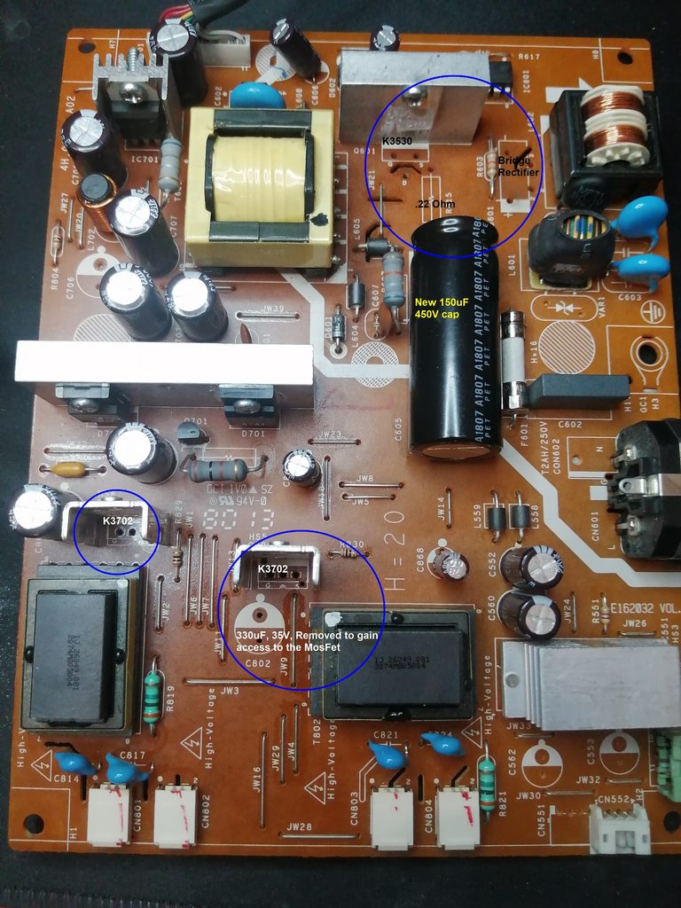
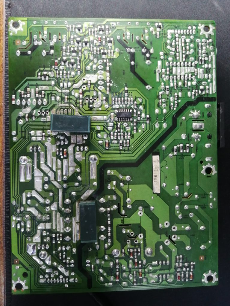
Here is the photo of the board with MosFets removed for testing, only the K3530 is short circuit and the 0.22 ohm resistor is open circuit (burnt). The bridge rectifier tests OK as do the other 2 MosFets and the removed cap as well.

I was unable to locate a new 120uF 450V cap, so I replaced with a 150uF 450V, this shouldn't make any difference, should it?

Does this help you at all?

EOvmUdvh.jpg
 
Check the switcher isn't dead, number on top should direct you to a Google spec. (ic601) 1/3 way in RHS top.

Is there a way that I can test this IC601 without powering it up then or do I need to provide external power from a bench supply and look for an output?
 
Check the number on Google for spec sheet and that will show what is inside the chip. Then you can test for shorts etc with no power via a standard multimeter.
 
Sir specmaster . . . . . . (+ or - 2 nanovolts ? )

I consulted post 7 . . .observed photos . . . . .wiped drool from my lips.
You have that single pulled power FET that drives that main power transformer to its left for giving 5 V standby . . . . . ALL of the time that the unit is plugged into AC wall power.
Seems like an additional 12 VDC is also derived .
Down at the bottom are two additional power FETS that also drive those two black inverter transformers that create HIGH voltage to drive your sets of back light mini Compact Fluorescent Lamps .
Leave those FETS uninstalled as they are initially of no concern to us.
I may have found a close enough ASUS schematic . . . a model 198 . . . . to work with . . . . give me their driver IC and it may be on bottom of chassis feeding their gates . . . . .packaged as a mini flat pack configuration.
NOW . . . in going back to your principal power supply . . .
Any chance that IC 601 . . . .an 8 pinner I.C. . . . . . is being a TEA1530AT . . . . if so, its Pin 6 outputs as gate drive to the frontal POWER FET.
BUT with that low ohmmage source fusible / resistor being open, a HELL of a source power hit it to open it, and with you possibly now finding a fused internal source to drain die . . . . that is now testing as DEAD shorted.
If testing as open, it may have all vaporized internally. If all melded together internally, initially, one could suspect the merged gate to source to drain, confluence, to have sent hundreds of volts backwards into the driver pin 6 to blow up its internal driver section.

If your unit uses a different IC 601, pass it to me, let me look it up.

Considering you also having AS MANY Ole'- silly- scopes .

EVALUATION . . .
. . . with no POWER FET reinstalled . . . . . upon A.C. power plug in, that I.C. should put out a serial burst of start up pulses to drive the FET initially. Then a dedicated run winding on the transformer outputs its low voltage power to a diode to be filtered an then that supply is the continual run voltage for the chip.
So if you scope pin 6 at AC power plug in time and see a numbered timing of start up pulses, you were / are LUCKY !
Then you get busy and put on yore BIG BOY pants and put in a good POWER FET and pull the fuse and use 2 hook up wire lengths to wire in a 60 watt incandescent lamp, in place of the fuse .
Power up with AC power plug in and see that the lamp doesn't go to FULL brightness . . . .instead it just having a possible, low glow.
More importantly, clip in and DC voltage monitor any one of the low voltage supply E-cap output filters at circuit boards top left corner. A slight voltage build up on it would indicate a successfully activated transformer output and the derived / but / being of a reduced voltage.(For such a short activation time )
And then . . . . .AND THEN . . . .AND THEN . . . . you might go for it . . . and try with the fuse reinstalled . . . to see if the monitored voltage COMES on UP.

Fill me in . . . .

73's De Edd . . . .

Life . . . . .

upload_2022-5-10_5-53-34.png

.


Sir specmaster . . . . . . (+ or - 2 nanovolts ? )

I consulted post 7 . . .observed photos . . . . .wiped drool from my lips.
You have that single pulled power FET that drives that main power transformer to its left for giving 5 V standby . . . . . ALL of the time that the unit is plugged into AC wall power.
Seems like an additional 12 VDC is also derived .
Down at the bottom are two additional power FETS that also drive those two black inverter transformers that create HIGH voltage to drive your sets of back light mini Compact Fluorescent Lamps .
Leave those FETS uninstalled as they are initially of no concern to us.
I may have found a close enough ASUS schematic . . . a model 198 . . . . to work with . . . . give me their driver IC and it may be on bottom of chassis feeding their gates . . . . .packaged as a mini flat pack configuration.
NOW . . . in going back to your principal power supply . . .
Any chance that IC 601 . . . .an 8 pinner I.C. . . . . . is being a TEA1530AT . . . . if so, its Pin 6 outputs as gate drive to the frontal POWER FET.
BUT with that low ohmmage source fusible / resistor being open, a HELL of a source power hit it to open it, and with you possibly now finding a fused internal source to drain die . . . . that is now testing as DEAD shorted.
If testing as open, it may have all vaporized internally. If all melded together internally, initially, one could suspect the merged gate to source to drain, confluence, to have sent hundreds of volts backwards into the driver pin 6 to blow up its internal driver section.

If your unit uses a different IC 601, pass it to me, let me look it up.

Considering you also having AS MANY Ole'- silly- scopes .

EVALUATION . . .
. . . with no POWER FET reinstalled . . . . . upon A.C. power plug in, that I.C. should put out a serial burst of start up pulses to drive the FET initially. Then a dedicated run winding on the transformer outputs its low voltage power to a diode to be filtered an then that supply is the continual run voltage for the chip.
So if you scope pin 6 at AC power plug in time and see a numbered timing of start up pulses, you were / are LUCKY !
Then you get busy and put on yore BIG BOY pants and put in a good POWER FET and pull the fuse and use 2 hook up wire lengths to wire in a 60 watt incandescent lamp, in place of the fuse .
Power up with AC power plug in and see that the lamp doesn't go to FULL brightness . . . .instead it just having a possible, low glow.
More importantly, clip in and DC voltage monitor any one of the low voltage supply E-cap output filters at circuit boards top left corner. A slight voltage build up on it would indicate a successfully activated transformer output and the derived / but / being of a reduced voltage.(For such a short activation time )
And then . . . . .AND THEN . . . .AND THEN . . . . you might go for it . . . and try with the fuse reinstalled . . . to see if the monitored voltage COMES on UP.

Fill me in . . . .

73's De Edd . . . .

Life . . . . .

View attachment 55131

.


Wow, thats pretty detailed, you must like repairing SMPS then eh?

Ok then IC601 is infact a 1203P60.

Instead of a 60W lamp inserted instead of the 2A fuse, how about fitting a new fuse and slowly bringing the power up via a variac?
 
The datasheet often gives a good insight to the operational aspects of the SMPS and here's the relevant bits for the 1203P60 device you mention:

If the MOSFET shorts or the driver fails 'high' then it can be seen that this will cause damage to the bridge rectifier and (potentially) any parts of the EMI flter components.

My suggestion to replace any 'definitely' dud parts PLUS the MOSFET and the driver chip should fix the issue without resortiing to detailed tests. I realise this is a 'hammer' view of repairs but the circuitry on the primary side is very 'basic' and not a lot else can go wrong - shorts on the secondary side (low voltage) are usually catered for by over-current protection/feedback on that 'side' of the circuitry and wouldn't normally cause failure on the primary side.

Download the datasheet yourself and see how they use it to develop the actual SMPS in use.

1203P60.png
 
Sir spec meister . . . . .
I am seeing an IC801 as being a 16 pin flat pack . . .surface mount and its final pins, 15 and 16 are providing separate gate drives to the two power FETS that drive the two black inverter HV transformers.
I am possibly suspicioning it to be of the SG38xx family . . . pls confirm.
I am also seeing the foil path taken from the 1203 to the gate of its power FET.

There are internal FIXED frequency operations of this 1203 chip at 40-60 and 100 khz . . .your chips end designator suffix is confirming your unit as being a 60 khz version.
Thaaaaaaaaaaaaasit

73's de Edd . . . . .
 

Attachments

  • upload_2022-5-10_10-32-37.png
    upload_2022-5-10_10-32-37.png
    150.9 KB · Views: 5
Last edited:
Sir spec meister . . . . .
I am seeing an IC801 as being a 16 pin flat pack . . .surface mount and its final pins, 15 and 16 are providing separate gate drives to the two power FETS that drive the two black inverter HV transformers.
I am possibly suspicioning it to be of the SG38xx family . . . pls confirm.
I am also seeing the foil path taken from the 1203 to the gate of its power FET.

There are internal FIXED frequency operations of this 1203 chip at 40-60 and 100 khz . . .your chips end designator suffix is confirming your unit as being a 60 khz version.
Thaaaaaaaaaaaaasit

73's de Edd . . . . .
Ok then, the IC801 is a OZ9938GN there is no connection between pin 5 and the Gate of the MosFet, probing with my Fluke 85 these 3 parts are completely open circuit
qvCw2jxh.jpg
 
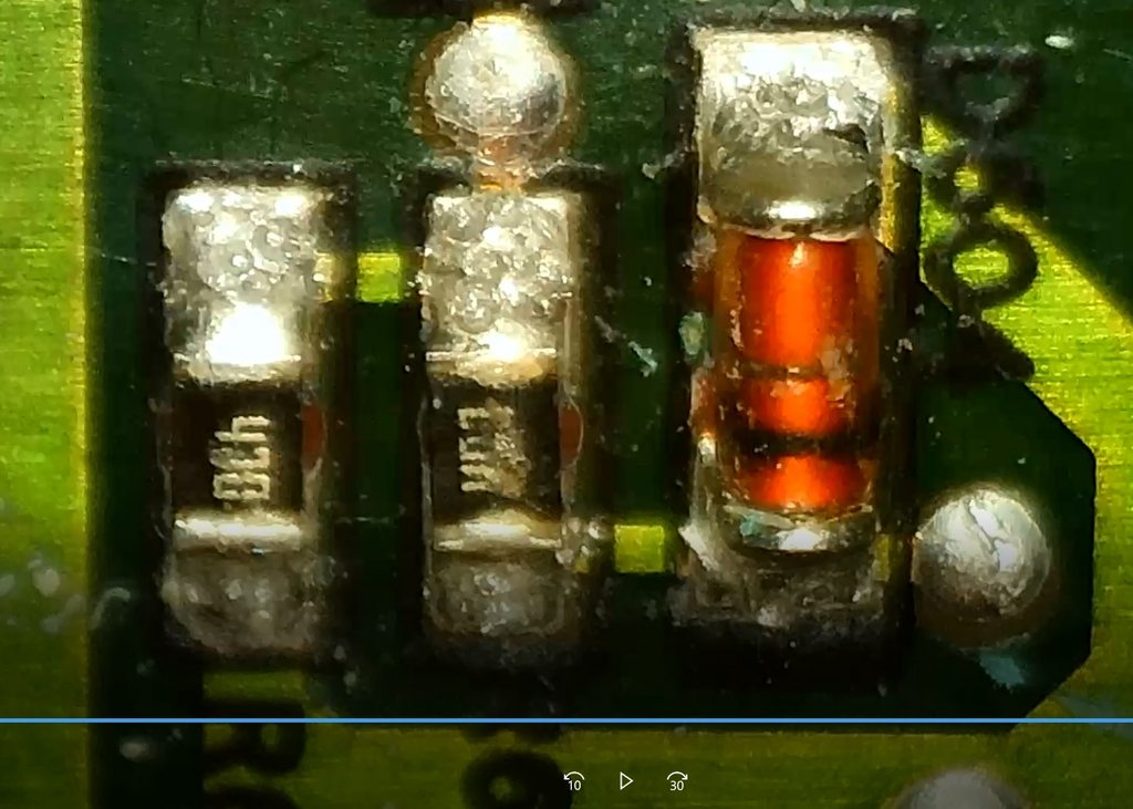
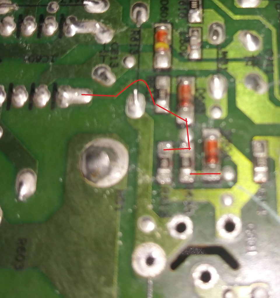
The three parts are respectively from left to right R612, R620 and D604, 2 resistors and a diode and there is continuity along the red line to the feed end of R612 and R620. R620 and the diode D604 are in series and the end of the diode and R612 terminate on the foil that connects to the gate.
xvV7zGrh.jpg
 
Correction to the above message, I must have had my meter in diode test mode, so my bad. Right, selecting diode mode on the meter, the diode seems to be ok and giving a reading of 0.6V in one direction and O/L in the other, so that appears to fine.

Switching over to resistance mode, R612 reads 53K (in circuit) and R620 (should read as R623) is open circuit and as a double check, the diode in resistance mode is reading 1.5M with negative to cathode and O/L with positive to cathode.

According to my research, so far, the 470 on R612 equates to 47 ohms so with it reading so high in circuit is an indication of it being either open circuit and the 53K is via another path through other devices, or it is badly damaged and reads that high so needs replacing.

R623, I'm unable to decipher what is written on the top, so currently clue less as to what its value should be.

I'm looking for the other manual you found (VW198) to see if that could provide a clue. Will report back later when I find it.
 
Last edited:
Top