I am building an Astrophotography Tracking Platform based off of this design.
http://www.garyseronik.com/?q=node/52
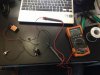
The circuit, at the bottom of the link above, looked simple enough for me to recreate. I have some limited electronics knowledge and have definitely done my fair share of Google searches in trying to learn how to do this.
The whole point of this box is to create a steady 3v for a DC motor attached to a gear. I wasn't quite sure how the voltage regulator worked, or how to wire the pot so I rigged everything together with some wire just to make sure that I had everything right before I created a PCB to permanently mount everything. With everything rigged up and with both leads connected to my multimeter I was able to get a very steady 3.000v from the circuit. I had a little concern at this point because I was very close to one of the limits on the pot to reach the 3v, as I turned the pot to the right the voltage steadily decreased from about 5.3v down to 2.89v.
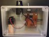
When I made the PCB and mounted everything inside the box I decided to test everything again to make sure I still had the 3v I needed. This time around though I couldn't get the voltage to drop below 3.2v. I checked the resistance that my pot was producing and it only had a range of about 500 to 234ohms. I found this table http://www.reuk.co.uk/LM317-Voltage-Calculator.htm that shows that I need the pot to produce 210ohms of resistance for the voltage regulator to output 3v.
It's my understanding that a 500ohm pot should have a range of 0 to 500ohms, which leads to my confusion about why I can't get the resistance down to the 210ohms that I need for the regulator.
The easiest solution, I think, would be to buy another pot, but I want to make sure it will do what I need before I spend another $10. I would appreciate any help that I can get.
Thanks,
T-Dog
http://www.garyseronik.com/?q=node/52
The circuit, at the bottom of the link above, looked simple enough for me to recreate. I have some limited electronics knowledge and have definitely done my fair share of Google searches in trying to learn how to do this.
The whole point of this box is to create a steady 3v for a DC motor attached to a gear. I wasn't quite sure how the voltage regulator worked, or how to wire the pot so I rigged everything together with some wire just to make sure that I had everything right before I created a PCB to permanently mount everything. With everything rigged up and with both leads connected to my multimeter I was able to get a very steady 3.000v from the circuit. I had a little concern at this point because I was very close to one of the limits on the pot to reach the 3v, as I turned the pot to the right the voltage steadily decreased from about 5.3v down to 2.89v.
When I made the PCB and mounted everything inside the box I decided to test everything again to make sure I still had the 3v I needed. This time around though I couldn't get the voltage to drop below 3.2v. I checked the resistance that my pot was producing and it only had a range of about 500 to 234ohms. I found this table http://www.reuk.co.uk/LM317-Voltage-Calculator.htm that shows that I need the pot to produce 210ohms of resistance for the voltage regulator to output 3v.
It's my understanding that a 500ohm pot should have a range of 0 to 500ohms, which leads to my confusion about why I can't get the resistance down to the 210ohms that I need for the regulator.
The easiest solution, I think, would be to buy another pot, but I want to make sure it will do what I need before I spend another $10. I would appreciate any help that I can get.
Thanks,
T-Dog

")

