Maker Pro
Maker Pro

Letting current flow only for an amount of time ?

Hello everyone,

i'm currently into a School project where i need to connect a smoke detector to a drill machine who will rotate some kind of a pump to get the water throwed into a specific direction. ( There is somekind of a fire extinguisher but not for real, just for school as they want to see how smart we are ).

And i am curently stuck on how can i let the current from the battery of the drilling machine flow only for an amount of time.

I was thinking of some kind of a timer that waits for a signal with a current from 0,5V to 9V (max output), and when the timer got the signal from the smoke detector it will let the current from the battery flow direct to the motor of the drill machine ( push button got removed ), just for an amount of time, like 50 seconds or something like that.

I did some kind of a schematic, but i really don't know how can i do that kind of timer, or what components do i need to do that.

Hpt4dvo.png


1 - Signal from the detector who Timer is waiting for.
2 - Output from the 18V current wich is allowed from the timer.
3 - Input of 18V ( battery )

So my question in final is: How can i do that timer ?
 
Last edited by a moderator:
If you are trying to rotate a motor to a specific angle by timing the power to it, it is not going to work very well. You need angular feedback to do this correctly.

Bob
 

davenn

Moderator
If you are trying to rotate a motor to a specific angle by timing the power to it

I don't think so ... as the drill is operating a pump so it will be turning for a period of time to pump water towards the fire
so its just needs to be timed on for xx minutes a then turned off
 
That depends on how you read the OP. I read is as there is a pump (with it's own motor) and the drill motor is used to
"rotate the pump to get the water throwed [sic] in a specific direction" (OP's wording),

But I can see your reading as well, where the pump is already pointed in the right direction and the drill motor is powering the pump.

OP - which is it?

Bob
 
The pomp is a simple one wich powered from the drill, i just opened the drill case, removed the button and connected the battery directly to the motor, and between baterry and motor i want to install this "timer" wich is operated by signal given from the smoke detector, that means when the "timer" recieves and signal "an current from 0,5V - 9V" it will allow the current from the battery to flow to the motor for an amount of time.

And what is OP? Sorry i am not an electrician or something, i worked with some electronics but not like this.

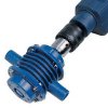
This is the pump i am talking about, so it doesn't have it's own motor, the motor is the drill:

41V3E487RDL._SX425_.jpg
 

davenn

Moderator
That depends on how you read the OP. I read is as there is a pump (with it's own motor) and the drill motor is used to
"rotate the pump to get the water throwed [sic] in a specific direction" (OP's wording),

he doesn't mention a motorised pump ... that's what the drill is for ;)
there quite a range of pump units that are driven directly from an electric drill

thWAWDW1HY.jpg


so a 555 timer triggered on by the smoke detector and timed to run for x period of time

a fun school project :)


D
 
he doesn't mention a motorised pump ... that's what the drill is for ;)
there quite a range of pump units that are driven directly from an electric drill

View attachment 23751


so a 555 timer triggered on by the smoke detector and timed to run for x period of time

a fun school project :)


D

Nice, it's first time when i hear about 555 timer IC, can you please explain or give me some kind of an example of an circuit ? But don't forget that the input power from the battery is 18V and the output must be 18V too. Just the input from the signal of the smoke detector is 0,5V to 9V.
 
OP = opening Post / Original Post

I would suggest for the project experiment that you use a low powered battery drill -- the around 10 - 20V variety
you really don't want to be messing with switching mains voltages !!

here's one circuit idea to start you off

View attachment 23752
I can't use a low voltage battery because the drill's motor runs only on 18V, so it comes from the manufacture. Or what do you mean by that?
 

davenn

Moderator
do some googling on 555 timers to learn about how to adjust the on time triggering etc

where that switch is on the left side is when the input from the smoke detector output would come from

the detector output .... is it a relay ?
a voltage .... if so, how many volts ?
 
do some googling on 555 timers to learn about how to adjust the on time triggering etc

where that switch is on the left side is when the input from the smoke detector output would come from

the detector output .... is it a relay ?
a voltage .... if so, how many volts ?

A no, the voltage from the smoke detector is not a relay, it is a fixed voltage but i couldn't measure it because of the incapacity of my teacher to bring me an voltmeter, but i am thinking somewhere at 1V to be the output from the smoke detector.

//Edit: on Thursday i will measure the voltage from the smoke detector output, and i will tell you here.
 

davenn

Moderator
I can't use a low voltage battery because the drill's motor runs only on 18V, so it comes from the manufacture. Or what do you mean by that?

18V drill ... exactly the type I was referring to :)
didn't want you messing with mains powered drill 120 / 240VAC

the timer could for the project run off a small 9V battery ... one of those small rectangular PP3 type
 

davenn

Moderator
A no, the voltage from the smoke detector is not a relay, it is a fixed voltage but i couldn't measure it because of the incapacity of my teacher to bring me an voltmeter, but i am thinking somewhere at 1V to be the output from the smoke detector.

OK is around 1V that would be an ideal trigger voltage

OK I need to leave ... time to go to work

go do some reading up on 555 timers ... google a data sheet
 
OK is around 1V that would be an ideal trigger voltage

OK I need to leave ... time to go to work

go do some reading up on 555 timers ... google a data sheet

Ok thank you very much, please check this topic again on Thursday maybe i can give you some exact data from the actual voltages. Thank you !
 

davenn

Moderator
You have not answered my question about your project. Is the drill motor used to power the pump or is it used to direct the pump to the place that it should be pumping?

Bob, please read the posts :)


the pic of the pump he showed in post # 5 is the same style as what I showed in post #6
The drill drives the pump :)

as he stated in post #4 to your Q

The pomp is a simple one wich powered from the drill, .....

This is the pump i am talking about, so it doesn't have it's own motor, the motor is the drill:


Dave
 
Sorry about that, I somehow missed all the posts after my last request for clarification. I hate it when people do that!

Bob
 
Sorry about that, I somehow missed all the posts after my last request for clarification. I hate it when people do that!

Bob
It was my fault that i didn't clarified you. After davenn's reply i started to answer him because he understood from the first point what i am talking about. My fault, i am sorry.
 
Just the input from the signal of the smoke detector is 0,5V to 9V.
Do you mean the detector output rises from 0.5V to 9V (i.e is a positive-going pulse edge) when smoke is detected? If so, to trigger a 555 timer IC at pin 2 you will need a transistor stage to provide a negative-going pulse signal.
 
Top